【频率域平滑、锐化滤波器】理想滤波器,巴特沃思滤波器,高斯滤波器
- 一、背景知识
- 二、理想滤波器原理及实现
- 1.理想低通滤波器
- 2.理想低通滤波器的实现:
- 3.理想高通滤波器:
- 三、巴特沃思滤波器原理及实现
- 1.巴特沃思低通滤波器
- 2.巴特沃思高通滤波器
- 三、高斯滤波器原理及实现
- 1.高斯低通滤波器:
- 2.高斯高通滤波器:
- 四、代码附录
- 五、结尾
一、背景知识
本文主要介绍频率域滤波器,此处的频率域是基于傅立叶变换得出。
在一幅图像中,低频对应图像变化缓慢的部分,即图像大致外观和轮廓。高频部分对应图像变化剧烈的部分即图像细节。低通滤波器的功能是让低频率通过而滤掉或衰减高频,其作用是过滤掉包含在高频中的噪声。即低通滤波的效果是图像去噪声平滑增强,但同时也抑制了图像的边界即过滤掉图像细节,造成图像不同程序上的模糊。
这里考虑三种滤波器,分别为理想滤波器、巴特沃思滤波器和高斯滤波器。这三种滤波器分别有其低通滤波器和高通滤波器。
这三种滤波器涵盖了从非常尖锐(理想)到非常平坦(高斯)范围的滤波器函数。巴特沃思滤波器有一个参数,称为滤波器的“阶数”。当此参数的值较高时,巴特沃思滤波器接近理想滤波器。因此,巴特沃思滤波器可看作两种“极端”滤波器的过渡。
二、理想滤波器原理及实现
1.理想低通滤波器
我们所想像的最简单的低通滤波器是“截断”傅里叶变换中所有高频部分,这些成分处在距变换原点的距离比指定距离D0要更远得多的位置。这种滤波器被称为二维理想低通滤波器(ILPF),其变换函数为:
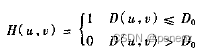
其中,D0是指定的非负数值,D(u,w)是(u,v)点距频率矩形原点的距离。如果要研究的图像尺寸为M*X,它的变换也有相同的尺寸,由于变换被中心化了,所以频率矩阵的中心在(u,v)=(M/2,N/2)处。在这种情况下,从点(u,v)到傅立叶变换中心的距离如下所示:(参照傅立叶变换和频率域)

需要注意理想低通滤波非常不实用,在使用中会产生“振铃”(输出图像的灰度剧烈变化处产生的震荡,就好像钟被敲击后产生的空气震荡)。然而,因为理想滤波器可以在计算机上实现,所以作为滤波概念发展的一部分,研究滤波器的特性非常有用。
2.理想低通滤波器的实现:
步骤一:将图像扩充为适合离散傅立叶变换的图像尺寸大小。
Mat Filter::ImageChangeForDft(const Mat & input)
{
    int width = getOptimalDFTSize(input.cols);
    int height = getOptimalDFTSize(input.rows);
    Mat output;
    copyMakeBorder(input,output,0,height-input.rows,0,width-input.cols,BORDER_CONSTANT,Scalar::all(0));
    output.convertTo(output,CV_32FC1);
    return output;
}
核心函数介绍:
int getOptimalDFTSize(int vecsize);
int类型的vecsize,向量尺寸,一般是图片的宽或高。
该函数可以自动计算最适合进行离散傅里叶变换的图像尺寸大小,从而提高计算速度。
CV_EXPORTS_W void copyMakeBorder(InputArray src, OutputArray dst, int top, int bottom, int left, int right,int borderType, const Scalar& value = Scalar() );
src:输入图像。 dst:输出图像(类型和输入图像类型一致,大小为:Size(src.cols+left+right,src.rows+top+bottom))。
top、bottom、left、 right: 这4个参数指定输出图像4个方向要扩展多少个像素,
bordertype:已拷贝的原图像长方形的边界的类型:IPL_BORDER_CONSTANT:填充边界为固定值,值由函数最后一个参数指定。
IPL_BORDER_REPLICATE:边界用上下行或者左右列来复制填充。
value:如果border==BORDER_CONSTANT,value为border value。
步骤二:根据公式截断,获得滤波器ILPF
Mat Filter::IdealLowKernel(Mat &input,const float sigma) {
    Mat result(input.size(),CV_32FC1);
    float d0=sigma;//半径D0越小,模糊越大;半径D0越大,模糊越小
    for(int i=0;i<input.rows ; i++ )
    {
        for(int j=0; j<input.cols ; j++ )
        {
            float d = sqrt(pow((i - input.rows/2),2) + pow((j - input.cols/2),2));//分子,计算pow必须为float型
            //d实际是到中心点的距离。
            if (d <= d0)
            {
                result.at<float>(i,j)=1;
            }
            else
            {
                result.at<float>(i,j)=0;
            }
        }
    }
    return result; }
float d = sqrt(pow((i - input.rows/2),2) + pow((j - input.cols/2),2))
注意:该公式是基于频谱居中后的频谱图进行到中心点的距离计算,所以dft之后需要将频谱居中再计算
理想低通滤波“截断”傅里叶变换中所有高频部分,这些成分处在距变换原点的距离比指定距离D0要更远得多的位置,根据点(u,v)到傅立叶变换中心的距离进行截断。
步骤三:空间域转频率域,与滤波器ILPF相乘,再转回空间域
Mat Filter::FrequencyFilter(Mat &input,Mat &blur)
{
    //first, from spatial domain to frequency domain
    Mat plane[] = {input , Mat::zeros(input.size() , CV_32FC1)};
    Mat dftMat;
    merge(plane,2,dftMat);
    dft(dftMat,dftMat);

    //second, shift frequency domain
    split(dftMat,plane);
//    plane[0] = plane[0](Rect(0, 0, plane[0].cols & -2, plane[0].rows & -2));//这里为什么&上-2具体查看opencv文档
//    //其实是为了把行和列变成偶数 -2的二进制是11111111.......10 最后一位是0

    //频谱居中,四个象限位置互换,其中Plane[0]为实部,Plane[1]为虚部
    int cx = plane[0].cols/2;
    int cy = plane[0].rows/2;

    Mat part1_r(plane[0],Rect(0,0,cx,cy));
    Mat part2_r(plane[0],Rect(cx,0,cx,cy));
    Mat part3_r(plane[0],Rect(0,cy,cx,cy));
    Mat part4_r(plane[0],Rect(cx,cy,cx,cy));

    Mat temp;
    part1_r.copyTo(temp);
    part4_r.copyTo(part1_r);
    temp.copyTo(part4_r);

    part2_r.copyTo(temp);
    part3_r.copyTo(part2_r);
    temp.copyTo(part3_r);

    Mat part1_i(plane[1],Rect(0,0,cx,cy));
    Mat part2_i(plane[1],Rect(cx,0,cx,cy));
    Mat part3_i(plane[1],Rect(0,cy,cx,cy));
    Mat part4_i(plane[1],Rect(cx,cy,cx,cy));

    part1_i.copyTo(temp);
    part4_i.copyTo(part1_i);
    temp.copyTo(part4_i);

    part2_i.copyTo(temp);
    part3_i.copyTo(part2_i);
    temp.copyTo(part3_i);

    //third, multipy filter kernel and dftMat
    Mat blur_r,blur_i,BLUR;
    multiply(plane[0], blur, blur_r); //滤波(实部与滤波器模板对应元素相乘)
    multiply(plane[1], blur,blur_i);//滤波(虚部与滤波器模板对应元素相乘)
    Mat plane1[]={blur_r, blur_i};
    merge(plane1,2,BLUR);//实部与虚部合并

    //last, from frequency domain to spatial domain
    idft( BLUR, BLUR);
    split(BLUR,plane);
    magnitude(plane[0],plane[1],plane[0]);
    normalize(plane[0],plane[0],1,0,CV_MINMAX);
    Mat result;
    normalize(plane[0], result, 0, 255, CV_MINMAX);
    return result;
}
基于以上算法,可以更换滤波器达到不同的图像增强效果。
3.理想高通滤波器:
剔除低频,即当d<=d0 时为0。
Mat Filter::IdealHighKernel(Mat &scr,float sigma)
{
    Mat result(scr.size(),CV_32FC1);
    float d0=sigma;
    for(int i=0;i<scr.rows ; i++ )
    {
        for(int j=0; j<scr.cols ; j++ )
        {
            double d = sqrt(pow((i - scr.rows/2),2) + pow((j - scr.cols/2),2));//分子,计算pow必须为float型
            if (d <= d0)
            {
                result.at<float>(i,j)=0;
            }
            else
            {
              result.at<float>(i,j)=1;
            }
        }
    }
    return result;
}
三、巴特沃思滤波器原理及实现
1.巴特沃思低通滤波器
n级巴特沃思低通滤波器(BLPF)的传递函数(且截止频率距原点的距离为D0)的定义如下:
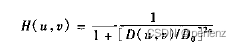
不同于ILPF,BLPF变换函数在通带与被滤除的频率之间没有明显的截断。对于有传递函数的滤波器,定义一个截止频率的位置并使H(u,v)幅度降到其最大值的一部分。在式中,当D(u,v)=D0时,H(u,v)=0.5(从最大值1降到它的50%)
一个一阶的巴特沃思滤波器没有振铃。在二阶中振铃通常很微小,但阶数增高的时候振铃变会成为一个重要的影响因素。阶数为5明显振铃和负值,阶数为20与ILPF相似。二阶的BLPF是在有效的低通滤波和可接受的振铃特性之间的折中。
Mat Filter::ButterworthLowKernel(Mat &scr,float sigma, int n)
{
    Mat result(scr.size(),CV_32FC1);
    double D0 = sigma;
    for(int i=0;i<scr.rows ; i++ )
    {
        for(int j=0; j<scr.cols ; j++ )
        {
            double d = sqrt(pow((i - scr.rows/2),2) + pow((j - scr.cols/2),2));
            result.at<float>(i,j)=1.0 / (1 + pow(d / D0, 2 * n));
        }
    }

    string name = "ButterworthLowKerneld0=" + std::to_string(sigma) + "n=" + std::to_string(n);
    imshow(name, result);
    return result;
}
2.巴特沃思高通滤波器
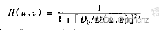
同低通滤波器情况一样,可以认为巴特沃思高通滤波器比IHPF更平滑。
Mat Filter::ButterworthHighKernel(Mat &scr,float sigma, int n)
{
    Mat result(scr.size(),CV_32FC1); //,CV_32FC1
    double D0 = sigma;
    for(int i=0;i<scr.rows ; i++ )
    {
        for(int j=0; j<scr.cols ; j++ )
        {
            double d = sqrt(pow((i - scr.rows/2),2) + pow((j - scr.cols/2),2));
            result.at<float>(i,j)=1.0 / (1 + pow(D0 / d, 2 * n));
        }
    }
    return result;
}
三、高斯滤波器原理及实现
1.高斯低通滤波器:
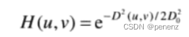
其中,D0是截止频率,D(u,v)是距频率矩形中心的距离。高斯滤波器的宽度由参数 D0 表征,决定了平滑程度,而且 D0越大,高斯滤波器的频带就越宽,平滑程度就越好。因为噪声主要集中在高频段,所以通过高斯低通滤波器可以滤除噪声信息、平滑图像,但与此同时会滤除图像的细节信息,使图像变得模糊。
Mat Filter::GaussianLowPassKernel(Mat scr,float sigma)
{
    Mat gaussianBlur(scr.size(),CV_32FC1);
    float d0=2*sigma*sigma;//高斯函数参数,越小,频率高斯滤波器越窄,滤除高频成分越多,图像就越平滑
    for(int i=0;i<scr.rows ; i++ )
    {
        for(int j=0; j<scr.cols ; j++ )
        {
            float d=pow(float(i-scr.rows/2),2)+pow(float(j-scr.cols/2),2);//分子,计算pow必须为float型
            gaussianBlur.at<float>(i,j)=expf(-d/d0);//expf为以e为底求幂(必须为float型)
        }
    }

    return gaussianBlur;
}
2.高斯高通滤波器:
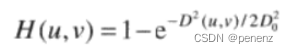
通过高斯高通滤波器可以增强细节信息,提升图像的高频分量,减少低频分量,对微小物体和细线条也能很好地增强显示。
Mat Filter::GaussianHighPassKernel(Mat scr,float sigma)
{
    Mat gaussianBlur(scr.size(),CV_32FC1); //,CV_32FC1
    float d0=2*sigma*sigma;
    for(int i=0;i<scr.rows ; i++ )
    {
        for(int j=0; j<scr.cols ; j++ )
        {
            float d=pow(float(i-scr.rows/2),2)+pow(float(j-scr.cols/2),2);//分子,计算pow必须为float型
            gaussianBlur.at<float>(i,j)=1-expf(-d/d0);
        }
    }
    return gaussianBlur;
}
通过公式里的傅立叶反变换得到的空间高斯滤波器将没有振铃。也是平时最为常用的滤波器。
四、代码附录
<filter.h>
#ifndef FILTER
#define FILTER

#include <iostream>
#include <opencv2/opencv.hpp>

class Filter
{
public:
    cv::Mat ImageChangeForDft(const cv::Mat & input);
    cv::Mat IdealLowKernel(cv::Mat &input,const float sigma);
    cv::Mat FrequencyFilter(cv::Mat &input,cv::Mat &blur);
    cv::Mat IdealLowPassFilter(const cv::Mat &input, float sigma);
    cv::Mat ButterworthLowKernel(cv::Mat &scr,float sigma, int n);
    cv::Mat ButterworthLowPassFilter(cv::Mat &src, float d0, int n);
    cv::Mat GaussianLowPassKernel(cv::Mat scr,float sigma);
    cv::Mat GaussianLowPassFilter(cv::Mat &src, float d0);
    cv::Mat IdealHighKernel(cv::Mat &scr,float sigma);
    cv::Mat IdealHighPassFilter(cv::Mat &src, float sigma);
    cv::Mat ButterworthHighKernel(cv::Mat &scr,float sigma, int n);
    cv::Mat ButterworthHighPaassFilter(cv::Mat &src, float d0, int n);
    cv::Mat GaussianHighPassKernel(cv::Mat scr,float sigma);
    cv::Mat GaussianHighPassFilter(cv::Mat &src, float d0);

};
<filter.cpp>
#include <iostream>
#include <opencv2/opencv.hpp>

#include "filter.h"

using namespace std;
using namespace cv;

Mat Filter::ImageChangeForDft(const Mat & input)
{
    int width = getOptimalDFTSize(input.cols);
    int height = getOptimalDFTSize(input.rows);
    Mat output;
    copyMakeBorder(input,output,0,height-input.rows,0,width-input.cols,BORDER_CONSTANT,Scalar::all(0));
    output.convertTo(output,CV_32FC1);
    return output;
}

//*****************理想低通滤波器******************
Mat Filter::IdealLowKernel(Mat &input,const float sigma)
{
    Mat result(input.size(),CV_32FC1);
    float d0=sigma;//半径D0越小,模糊越大;半径D0越大,模糊越小
    for(int i=0;i<input.rows ; i++ )
    {
        for(int j=0; j<input.cols ; j++ )
        {
            float d = sqrt(pow((i - input.rows/2),2) + pow((j - input.cols/2),2));//分子,计算pow必须为float型
            //d实际是到中心点的距离。
            if (d <= d0)
            {
                result.at<float>(i,j)=1;
            }
            else
            {
                result.at<float>(i,j)=0;
            }
        }
    }
    return result;
}

Mat Filter::FrequencyFilter(Mat &input,Mat &blur)
{
    //first, from spatial domain to frequency domain
    Mat plane[] = {input , Mat::zeros(input.size() , CV_32FC1)};
    Mat dftMat;
    merge(plane,2,dftMat);
    dft(dftMat,dftMat);

    //second, shift frequency domain
    split(dftMat,plane);
//    plane[0] = plane[0](Rect(0, 0, plane[0].cols & -2, plane[0].rows & -2));//这里为什么&上-2具体查看opencv文档
//    //其实是为了把行和列变成偶数 -2的二进制是11111111.......10 最后一位是0

    //频谱居中,四个象限位置互换,其中Plane[0]为实部,Plane[1]为虚部
    int cx = plane[0].cols/2;
    int cy = plane[0].rows/2;

    Mat part1_r(plane[0],Rect(0,0,cx,cy));
    Mat part2_r(plane[0],Rect(cx,0,cx,cy));
    Mat part3_r(plane[0],Rect(0,cy,cx,cy));
    Mat part4_r(plane[0],Rect(cx,cy,cx,cy));

    Mat temp;
    part1_r.copyTo(temp);
    part4_r.copyTo(part1_r);
    temp.copyTo(part4_r);

    part2_r.copyTo(temp);
    part3_r.copyTo(part2_r);
    temp.copyTo(part3_r);

    Mat part1_i(plane[1],Rect(0,0,cx,cy));
    Mat part2_i(plane[1],Rect(cx,0,cx,cy));
    Mat part3_i(plane[1],Rect(0,cy,cx,cy));
    Mat part4_i(plane[1],Rect(cx,cy,cx,cy));

    part1_i.copyTo(temp);
    part4_i.copyTo(part1_i);
    temp.copyTo(part4_i);

    part2_i.copyTo(temp);
    part3_i.copyTo(part2_i);
    temp.copyTo(part3_i);

    //third, multipy filter kernel and dftMat
    Mat blur_r,blur_i,BLUR;
    multiply(plane[0], blur, blur_r); //滤波(实部与滤波器模板对应元素相乘)
    multiply(plane[1], blur,blur_i);//滤波(虚部与滤波器模板对应元素相乘)
    Mat plane1[]={blur_r, blur_i};
    merge(plane1,2,BLUR);//实部与虚部合并

    //last, from frequency domain to spatial domain
    idft( BLUR, BLUR);
    split(BLUR,plane);
    magnitude(plane[0],plane[1],plane[0]);
    normalize(plane[0],plane[0],1,0,CV_MINMAX);
    Mat result;
    normalize(plane[0], result, 0, 255, CV_MINMAX);
    return result;
}

//理想低通滤波器
Mat Filter::IdealLowPassFilter(const Mat &input, float sigma)
{
    Mat padded = ImageChangeForDft(input);
    Mat ideal_kernel=IdealLowKernel(padded,sigma);
    Mat result = FrequencyFilter(padded,ideal_kernel);
    return result;
}


Mat Filter::ButterworthLowKernel(Mat &scr,float sigma, int n)
{
    Mat result(scr.size(),CV_32FC1);
    double D0 = sigma;
    for(int i=0;i<scr.rows ; i++ )
    {
        for(int j=0; j<scr.cols ; j++ )
        {
            double d = sqrt(pow((i - scr.rows/2),2) + pow((j - scr.cols/2),2));
            result.at<float>(i,j)=1.0 / (1 + pow(d / D0, 2 * n));
        }
    }

    string name = "ButterworthLowKerneld0=" + std::to_string(sigma) + "n=" + std::to_string(n);
    imshow(name, result);
    return result;
}

//巴特沃斯低通滤波器
Mat Filter::ButterworthLowPassFilter(Mat &src, float d0, int n)
{
    //H = 1 / (1+(D/D0)^2n)    n表示巴特沃斯滤波器的次数
    //阶数n=1 无振铃和负值    阶数n=2 轻微振铃和负值  阶数n=5 明显振铃和负值   阶数n=20 与ILPF相似
    Mat padded = ImageChangeForDft(src);
    Mat butterworth_kernel=ButterworthLowKernel(padded,d0, n);
    Mat result = FrequencyFilter(padded,butterworth_kernel);
    return result;
}

Mat Filter::GaussianLowPassKernel(Mat scr,float sigma)
{
    Mat gaussianBlur(scr.size(),CV_32FC1);
    float d0=2*sigma*sigma;//高斯函数参数,越小,频率高斯滤波器越窄,滤除高频成分越多,图像就越平滑
    for(int i=0;i<scr.rows ; i++ )
    {
        for(int j=0; j<scr.cols ; j++ )
        {
            float d=pow(float(i-scr.rows/2),2)+pow(float(j-scr.cols/2),2);//分子,计算pow必须为float型
            gaussianBlur.at<float>(i,j)=expf(-d/d0);//expf为以e为底求幂(必须为float型)
        }
    }

    return gaussianBlur;
}

//高斯低通
Mat Filter::GaussianLowPassFilter(Mat &src, float d0)
{
    Mat padded = ImageChangeForDft(src);
    Mat gaussian_kernel=GaussianLowPassKernel(padded,d0);//理想低通滤波器
    Mat result = FrequencyFilter(padded,gaussian_kernel);
    return result;
}

Mat Filter::IdealHighKernel(Mat &scr,float sigma)
{
    Mat result(scr.size(),CV_32FC1);
    float d0=sigma;
    for(int i=0;i<scr.rows ; i++ )
    {
        for(int j=0; j<scr.cols ; j++ )
        {
            double d = sqrt(pow((i - scr.rows/2),2) + pow((j - scr.cols/2),2));//分子,计算pow必须为float型
            if (d <= d0)
            {
                result.at<float>(i,j)=0;
            }
            else
            {
              result.at<float>(i,j)=1;
            }
        }
    }
    return result;
}

//理想高通滤波器
Mat Filter::IdealHighPassFilter(Mat &src, float sigma)
{
    Mat padded = ImageChangeForDft(src);
    Mat ideal_kernel=IdealHighKernel(padded,sigma);
    Mat result = FrequencyFilter(padded,ideal_kernel);
    return result;
}

Mat Filter::ButterworthHighKernel(Mat &scr,float sigma, int n)
{
    Mat result(scr.size(),CV_32FC1); //,CV_32FC1
    double D0 = sigma;
    for(int i=0;i<scr.rows ; i++ )
    {
        for(int j=0; j<scr.cols ; j++ )
        {
            double d = sqrt(pow((i - scr.rows/2),2) + pow((j - scr.cols/2),2));
            result.at<float>(i,j)=1.0 / (1 + pow(D0 / d, 2 * n));
        }
    }
    return result;
}

//巴特沃斯高通滤波器
Mat Filter::ButterworthHighPaassFilter(Mat &src, float d0, int n)
{
    //H = 1 / (1+(D0/D)^2n)    n表示巴特沃斯滤波器的次数
    Mat padded = ImageChangeForDft(src);
    Mat butterworth_kernel=ButterworthHighKernel(padded,d0, n);
    Mat result = FrequencyFilter(padded,butterworth_kernel);
    return result;
}

Mat Filter::GaussianHighPassKernel(Mat scr,float sigma)
{
    Mat gaussianBlur(scr.size(),CV_32FC1); //,CV_32FC1
    float d0=2*sigma*sigma;
    for(int i=0;i<scr.rows ; i++ )
    {
        for(int j=0; j<scr.cols ; j++ )
        {
            float d=pow(float(i-scr.rows/2),2)+pow(float(j-scr.cols/2),2);//分子,计算pow必须为float型
            gaussianBlur.at<float>(i,j)=1-expf(-d/d0);
        }
    }
    return gaussianBlur;
}

//高斯高通
Mat Filter::GaussianHighPassFilter(Mat &src, float d0)
{
    Mat padded = ImageChangeForDft(src);
    Mat gaussian_kernel=GaussianHighPassKernel(padded,d0);//理想低通滤波器
    Mat result = FrequencyFilter(padded,gaussian_kernel);
    return result;
}

#endif
五、结尾
至此还可以引出其他拓展点:
如频率域的锐化滤波器还有拉普拉斯算子等、同时还有钝化模板、高频提升滤波和高频加强滤波、同态滤波器等
最后
以上就是机灵黄豆最近收集整理的关于【图像处理:频率域平滑与锐化】理想滤波器,巴特沃思滤波器,高斯滤波器一、背景知识二、理想滤波器原理及实现三、巴特沃思滤波器原理及实现三、高斯滤波器原理及实现四、代码附录五、结尾的全部内容,更多相关【图像处理:频率域平滑与锐化】理想滤波器内容请搜索靠谱客的其他文章。


![[数字图像处理]频域滤波(2)--高通滤波器,带阻滤波器与陷波滤波器](https://www.shuijiaxian.com/files_image/reation/bcimg11.png)

发表评论 取消回复