一、实验目的
掌握有限状态机的编程和使用方法。
二、实验内容
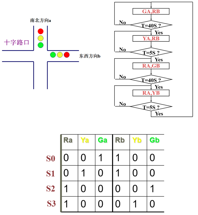
设计一个十字路口交通灯控制器,东西(b)、南北(a)方向有红灯、黄灯、绿灯,持续时间分别为45、5、40秒,仿真验证其功能。
三、实验设计与结果
1.整体设计思路:根据题目要求可知,需要用VHDL描述设计不同的进程分别进行“复位清零”、“状态定义及转化”、“时间定义及控制”、“计时”的功能。而又因为红绿灯需要持续40秒,而黄灯只需要持续5秒,因此需要将“时间的定义及控制”、“计时”的功能各自都分开成两个部分。细节:需要注意复位清零的异步性、双向红绿灯存在的4种不同状态、计时功能与状态选择的衔接等。VHDL描述代码如下。
①引入与定义:
LIBRARY ieee;
USE ieee.std_logic_1164.ALL;
USE ieee.std_logic_unsigned.ALL;

ENTITY rgy3 is
	port( clk,rst: in std_logic;
		Ra,Rb,Ga,Gb,Ya,Yb: out std_logic);
END rgy3;

Architecture bhv of rgy3 is
	type state is (S0,S1,S2,S3);
	signal presentstate,nextstate : state;
	signal time40,time5 : std_logic;
	signal rst40,rst5 : std_logic ;
	signal en40,en5 : std_logic ;
	signal tmp40 : std_logic_vector(5 downto 0);
	signal tmp5 : std_logic_vector(2 downto 0);
	begin
②异步复位清零:
	process(clk,rst)
	begin
	if rst = '1' then presentstate <= S0;
	elsif clk'event and clk='1' then
		presentstate<=nextstate;
	end if;
	end process;
③40秒计时:
process(clk,rst40,en40)
	begin
	    if rst = '1' then tmp40<="000000";
	    elsif rst40='1' then tmp40<="000000";
        elsif clk'event and clk='1' then
			if en40='1' then
				if tmp40="100111" then tmp40<="000000";
				else tmp40<=tmp40+1;
		        end if;
			end if;
	    end if;
	 if tmp40="100111" then time40<='1';
	 else time40<='0';
	 end if;
	end process;
④5秒计时:
	process(clk,rst5,en5)
	begin
		if rst = '1' then tmp5<="000";
        elsif rst5='1' then tmp5<="000";
        elsif clk 'event and clk='1' then
			if en5='1' then
				if tmp5="100" then tmp5<="000";
				else tmp5<=tmp5+1;
				end if;
			end if;
        end if;
        if tmp5="100" then time5<='1';
        else time5<='0';
        end if;
	end process;
⑤时间与状态衔接:
process(presentstate,time40,time5)
	begin
    case presentstate is
		when S0 => rst40 <='0';en40<='1';rst5<='1';en5<='0';
		if time40= '1' then nextstate<= S1;else nextstate<= S0;
		end if;
		when S1 => rst5 <='0';en5 <='1';rst40<='1';en40<='0';
	  	if time5= '1' then nextstate<= S2;else nextstate<= S1;
		end if;
		when S2 => rst40 <='0';en40<='1';rst5<='1';en5<='0';
		if time40= '1' then nextstate<= S3;else nextstate<= S2;
		end if;
		when S3 => rst5 <='0';en5<='1';rst40<='1';en40<='0';
		if time5= '1' then nextstate<= S0;else nextstate<= S3;
		end if;
	end case;
	end process;
⑥状态对应转化:
process(presentstate)
	begin
	case presentstate is
         when S0 	=>   Ra<='0'; Ya<= '0'; Ga<='1'; Rb<='1'; Yb<= '0'; Gb<='0';
         when S1 	=>   Ra<='0'; Ya<= '1'; Ga<='0'; Rb<='1'; Yb<= '0'; Gb<='0';
         when S2 	=>   Ra<='1'; Ya<= '0'; Ga<='0'; Rb<='0'; Yb<= '0'; Gb<='1';
         when S3	=>   Ra<='1'; Ya<= '0'; Ga<='0'; Rb<='0'; Yb<= '1'; Gb<='0';
	end case;
	end process;
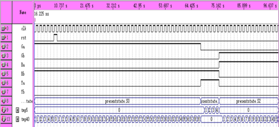
2.仿真实验:输入:clk、rst,输出:Ra、Rb、Ga、Gb、Ya、Yb以及状态中间输出:presentstate、tmp40、tmp5。
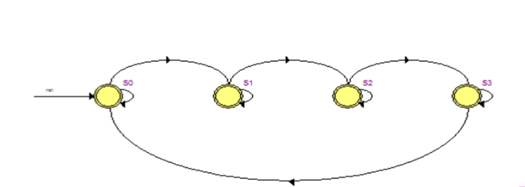
3.状态机转换图。
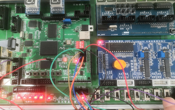
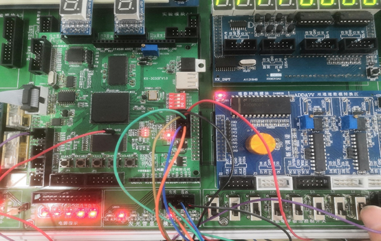
4.根据引脚配置完成接线,下载至FPGA芯片中,在实验箱上完成验证。如下图为相关的实验验证。
前些天发现了一个巨牛的人工智能学习电子书,通俗易懂,风趣幽默,无广告,忍不住分享一下给大家。(点击跳转人工智能学习资料)
四、实验思考与小结
1.VHDL描述的模块化,将实现不同功能的VHDL描述分开在不同的进程里面,实现VHDL的“高内聚低耦合”。
2. 需要明确不同的状态机它们之间的转换条件。
3. 状态机由状态寄存器和组合逻辑电路构成,能够根据控制信号按照预先设定的状态进行状态转移,是协调相关信号动作、完成特定操作的控制中心。交通信号灯可以用状态机的原理来实现,因为信号灯的变化状态是有限的,各个状态可以列举出来,状态间切换由计数器决定。
以下请忽略!
import numpy as np
import matplotlib.pyplot as plt
import matplotlib
list=[[1,2,3,4,5,6],[2,4,6,8,10,12],[1,3,5,7,9,11],[1.1,2.2,3.3,4.4,5.5,6.6],[3,6,9,12,15,18],[4,8,12,16,20,24
],[5,10,15,20,25,30],[1.5,2.5,3.5,4.5,5.5,6.5],[1,4,7,10,13,16],[2,5,8,11,14,17]]
a=np.array(list)
std=[]
avg=[]
x=[1,2,3,4,5,6,7,8,9,10]
for i in range(0,len(list)):
    std.append(np.std(a[i]))
    avg.append(np.mean(a[i]))
fig=plt.figure()
plt.xticks(x,x)
plt.plot(x,avg,marker="o",color='#858687',markeredgecolor='black',linewidth=3,label="Mean Value")
for i in range(len(avg)):
    plt.text(x[i],avg[i],avg[i],fontsize=10)
y1=[]
y2=[]
for i in range(len(x)):
    y1.append(avg[i]+std[i]/2)
    y2.append(avg[i] - std[i] / 2)
plt.fill_between(x,y1,y2,color='#d2e3f0',label="Standard deviation")
plt.grid()
plt.legend(loc=2)
plt.show()
最后
以上就是花痴山水最近收集整理的关于FPGA(7)--有限状态机--交通灯的全部内容,更多相关FPGA(7)--有限状态机--交通灯内容请搜索靠谱客的其他文章。


发表评论 取消回复