文章目录
- 前言
- 一、module的结构
- 1.1 module的申明
- 1.2 module的调用
- 二、参数传递方式
- 2.1 位置传参
- 2.2 参数名传参
- 三、嵌套多个模块
- 3.1 简单模块嵌套
- 3.2 复杂模块嵌套
- 四、加法器
- 4.1 Adder(1)
- 4.2 Adder(2)
- 4.3 Adder(3)
- 4.4 Adder(4)
- 总结
前言
前面课程我们已经熟悉了模块,在模块中,我们实现了各种逻辑功能。本文我们将深入讨论和学习模块。
一、module的结构
模块是一个电路,通过输入和输出端口与其外部交互。更大、更复杂的电路是通过将模块嵌套其他子模块,而子模块又是assign语句块和always语句块组成的。这就形成了一个层次结构,因为模块可以包含其他模块的实例。
1.1 module的申明
模块申明格式:
module 模块名(input 输入端口名,output 输出端口名);
模块体
endmodule
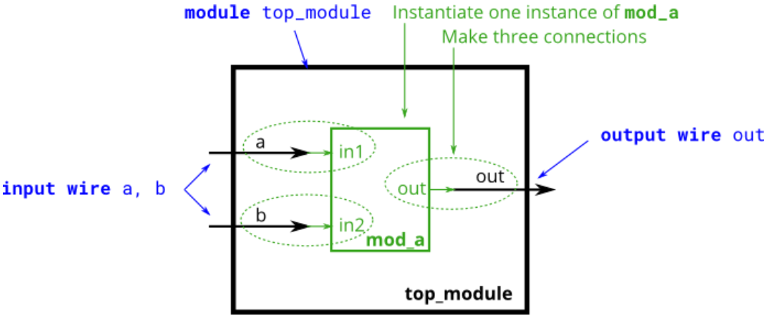
如以下代码中mod_a是图1中的子模块,有三个端口,两个输入端口in1、in2,一个输出端口out。
module mod_a ( input in1, input in2, output out );
    // Module body
endmodule
1.2 module的调用
要实现图1中顶层模块top_module调用实例化的子模块mod_a,需要编写以下代码:
module top_module ( input a, input b, output out );
mod_a instance1 (a, b, out);
endmodule
工程师经验:
- 模块名称符合命名规则,在verilog语法基础中有讲解,特别注意命名要有意义,要见名知意,通过下划线连接;
- 实际的模块定义中,都包括输入输出,没有输入输出,就没有办法与其他模块交互;
- 模块定义时的端口列表中的端口,可以看做c语言函数定义中的形式参数,如mod_a中的in1、in2、out,以及top_module定义中的a、b、out。实例化模块的端口列表中的端口,可以看做c语言函数调用中的实际参数,如实例化mod_a中传入的a、b、out;
- 模块可以嵌套调用,也就是模块中嵌套的是实例化的子模块。不能嵌套定义,比如模块中定义模块;
- 模块实例化时,要另取一个名字,比如module的调用中,mod_a另取名字instance1。在后面的小节中将使用同一个模块,实例化多个模块,这些模块通过名字区分;
- 一般项目中,使用一个顶层模块调用其他多个子模块;
二、参数传递方式
2.1 位置传参
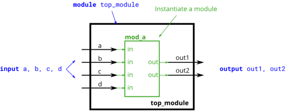
模块mod_a的定义如下:
module mod_a ( output out1, output out2, input in1, input in2, input in3, input in4);
// Module body
endmodule
顶层模块调用如下:
module top_module (
    input  a   ,
    input  b   ,
    input  c   ,
    input  d   ,
    output out1,
    output out2
);
mod_a instance1(out1, out2, a, b, c, d);
endmodule
在参数传递过程中,参数的位置一定要匹对,否则会出现意想不到的错误。工程中,一般不建议使用位置传递参数的方式,进行值传递。
2.2 参数名传参
顶层模块top_module调用的mod_a和2.1中的mod_a一致,但是通过参数名传递。
注意:参数名前有点(.)号,参数名紧跟的是(实际参数)。
module top_module (
    input  a   ,
    input  b   ,
    input  c   ,
    input  d   ,
    output out1,
    output out2
);
mod_a instance1(.out1  (out1),
                .out2  (out2),
                .in1   (a)   ,
                .in2   (b)   ,
                .in3   (c)   ,
                .in4   (d));
endmodule
实际工程中推荐使用的参数传递方式。
三、嵌套多个模块
3.1 简单模块嵌套
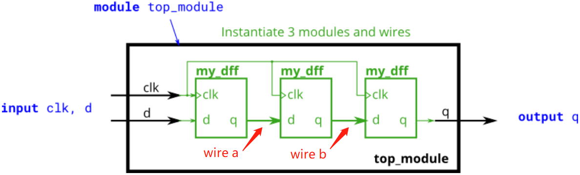
模块my_dff是一个D触发器(D flip-flop),定义如下:
module my_dff(input clk, input d, output q);
//Module body
endmodule
通过顶层模块top_module调用三个my_dff模块,代码如下:
module top_module ( input clk, input d, output q );
wire a;
wire b;
my_dff instance1(.clk  (clk),
                 .d    (d)  ,
                 .q    (a));//触发器instance1
my_dff instance2(.clk  (clk),
                 .d    (a)  ,
                 .q    (b));//触发器instance2
my_dff instance3(.clk  (clk),
                 .d    (b)  ,
                 .q    (q));//触发器instance3
endmodule
三个触发器模块连接起来,需要两个wire,所以定义两个中间wire a和b,触发器将会在后期作品中讲解。
3.2 复杂模块嵌套
在复杂的嵌套模块中,输入输出的情况不再是单个比特,同样是实例化三个模块my_dff8,中间wire a、b、c以及输入d的值都为8位。sel信号驱动4-1选择器,选择性将a、b、c、d赋值给输出q。原理图如下:
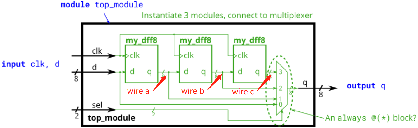
module my_dff8(input         clk,
               input  [7:0]  d  ,
               output [7:0]  q );
//Module body
endmodule
根据原理图编写的代码如下:
module top_module (
    input 		  clk,
    input  [7:0]  d  ,
    input  [1:0]  sel,
    output [7:0]  q
);
wire [7:0] a;
wire [7:0] b;
wire [7:0] c;
my_dff8 instance1 (.clk	(clk),
                   .d   (d)  ,
                   .q   (a));
my_dff8 instance2 (.clk	(clk),
                   .d	(a)	 ,
                   .q	(b));
my_dff8 instance3 (.clk	(clk),
                   .d	(b)  ,
                   .q	(c));
always@(*)begin
    case(sel)
        2'd0:	q = d;
        2'd1:	q = a;
        2'd2:	q = b;
        2'd3:	q = c;
    default:;
    endcase
end
endmodule
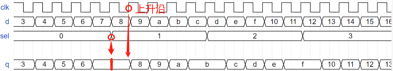
因为是4-1选择器,有4种情况,所以sel位宽为4。sel从0到3改变,但是q并没有根据d马上改变,是因为my_dff8是D触发器,是在时钟上升沿时候触发,所以延迟了一个时钟周期。
四、加法器
4.1 Adder(1)
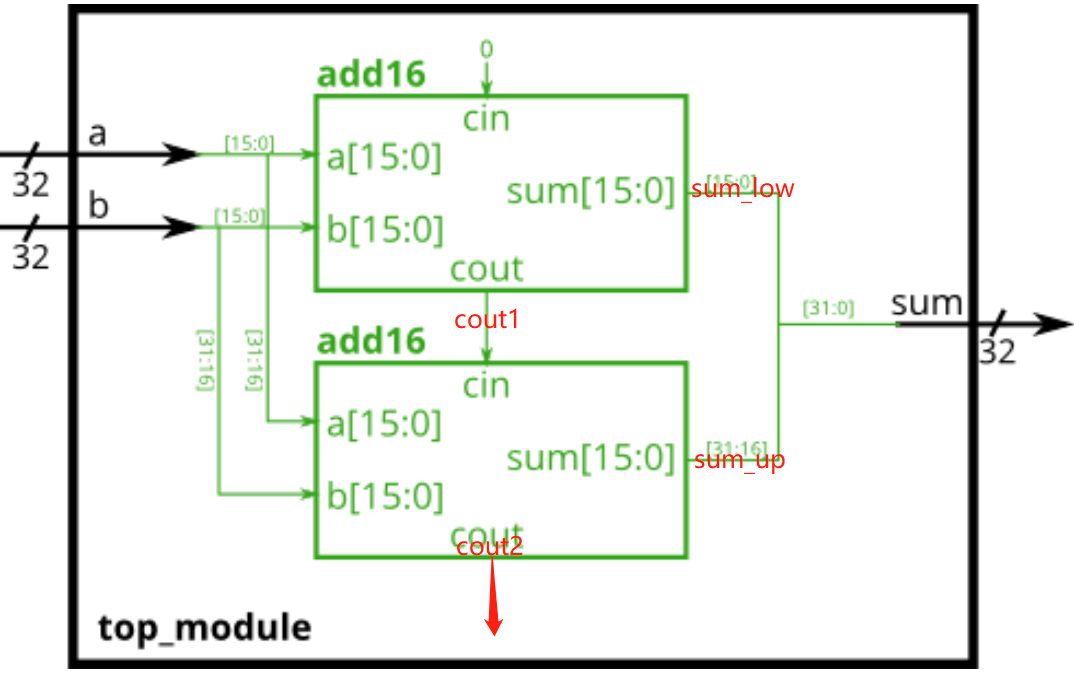
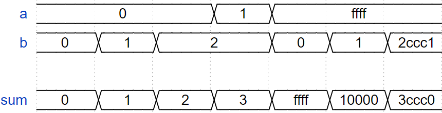
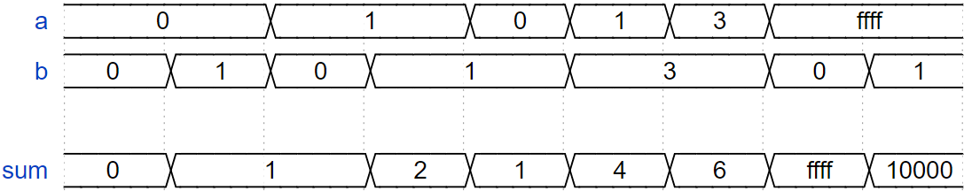
在模块top_module中实例化两个add16,创建一个32位加法器。一个add16模块计算加法结果的低16位,第二个add16模块在收到第一个加法器的结果后,计算结果的高16位。cin默认传入0。
module add16(input	[15:0]  a  ,
             input	[15:0]  b  ,
             input		    cin,
             output	[15:0]  sum,
             output         cout);
//Module body
endmodule
module top_module(
    input  [31:0] a,
    input  [31:0] b,
    output [31:0] sum
);
wire [15:0] sum_low;
wire [15:0] sum_up ;
wire 		cout1  ;
wire 		cout2  ;
add16 instance1(.a		(a[15:0]),
                .b		(b[15:0]),
                .cin	(1'b0)	 ,
                .sum	(sum_low),
                .cout	(cout1));
add16 instance2(.a		(a[31:16]),
                .b		(b[31:16]),
                .cin	(cout1)   ,
                .sum	(sum_up)  ,
                .cout	(cout2));
assign sum = {sum_up, sum_low};
endmodule
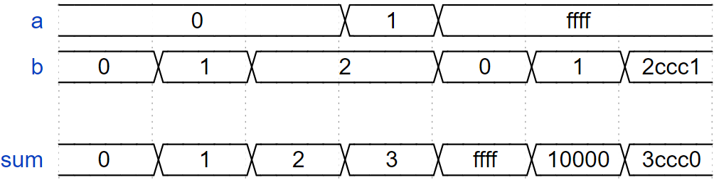
4.2 Adder(2)
创建一个具有两个模块的电路。top_module实例化两个add16,每个将实例化addr16包括16个实例化的add1。一个add16模块计算加法结果的低16位,第二个add16模块在收到第一个加法器的结果后,计算结果的高16位。cin默认传入0。
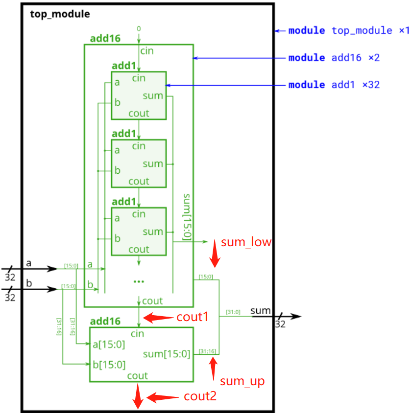
module top_module(
    input [31:0] a,
    input [31:0] b,
    output [31:0] sum
);

wire [15:0] sum_low;
wire [15:0] sum_up ;
wire 		cout1  ;
wire 		cout2  ;

add16 instance1(.a		(a[15:0]),
                .b		(b[15:0]),
                .cin	(1'b0)	 ,
                .sum	(sum_low),
                .cout	(cout1));
add16 instance2(.a		(a[31:16]),
                .b		(b[31:16]),
                .cin	(cout1)   ,
                .sum	(sum_up)  ,
                .cout	(cout2));
assign sum = {sum_up, sum_low};
endmodule
module add1 ( input a, input b, input cin,   output sum, output cout );

// Full adder module here
assign sum = a ^ b ^ cin;
assign cout = a&b | a&cin | b&cin;
endmodule
4.3 Adder(3)
Adder(2)中的加法器计算进位的延迟相当慢,而且在第一级加法器完成运算之前,第二级加法器不能开始计算它的进位。这使得加法器变慢。一个改进是进位选择加法器,如下所示。第一级加法器与之前相同,只是复制了第二级加法器,一个假设carry-in为0,另一个假设carry-in为1,然后使用一个快速的2对1多路复用器来选择哪个结果恰好是正确的。
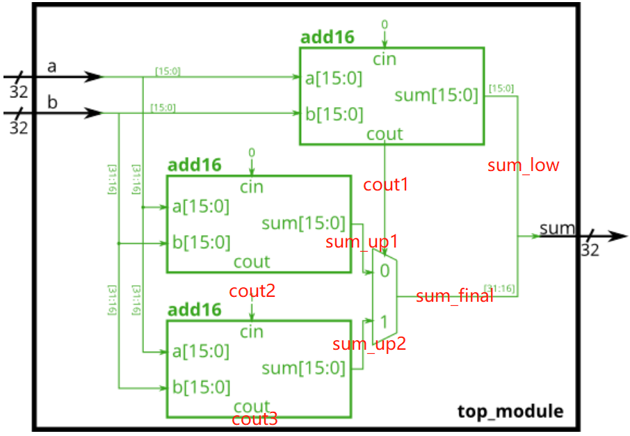
module top_module(
    input [31:0] a,
    input [31:0] b,
    output [31:0] sum
);

wire cout1;
wire cout2;
wire cout3;
wire [15:0] sum_low  ;
wire [15:0] sum_up1  ;
wire [15:0] sum_up2  ;
wire [15:0] sum_final;

add16 instance1(.a		(a[15:0]),
                .b		(b[15:0]),
                .cin	(1'b0)   ,
                .sum	(sum_low),
                .cout	(cout1));
add16 instance2(.a		(a[31:16]),
                .b		(b[31:16]),
                .cin	(1'b0)    ,
                .sum	(sum_up1) ,
                .cout	(cout2));
add16 instance3(.a		(a[31:16]),
                .b		(b[31:16]),
                .cin	(1'b1)    ,
                .sum	(sum_up2) ,
                .cout	(cout3));
always@(*)begin
    case(cout1)
        1'd0:	sum_final = sum_up1;
        1'd1:	sum_final = sum_up2;
        default:;
    endcase
end
assign sum = {sum_final, sum_low};
endmodule
4.4 Adder(4)
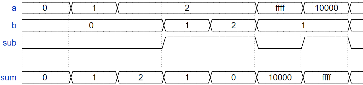
一个加法器是可以处理正负数的,对负数进行操作,可以看成将输入求反,然后加1。最终的结果是一个电路可以做两种操作:(a + b + 0)和(a + ~b + 1)。如图12中,sub为1的时候表示b输入的是负数,执行的操作是(a + ~b + 1),sub为0的时候表示b输入的是负数,执行的操作是(a + b + 0)。因为b是32位,所以sub会进行32次位复制。
- 当sub为1的时候,{32{sub}}和b进行异或,相当于对b求反;
- 当sub为0的时候,{32{sub}}和b进行异或,相当于b不变;
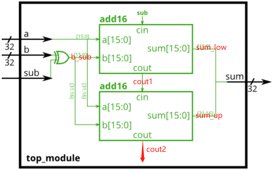
module top_module(
    input  [31:0] a  ,
    input  [31:0] b  ,
    input 		  sub,
    output [31:0] sum
);
wire [15:0] sum_low;
wire [15:0] sum_up ;
wire [31:0]	b_sub  ;
wire 		cout1  ;
wire 		cout2  ;

add16 instance1(.a		(a[15:0])    ,
                .b		(b_sub[15:0]),
                .cin	(sub)	     ,
                .sum	(sum_low)    ,
                .cout	(cout1));

add16 instance2(.a		(a[31:16])    ,
                .b		(b_sub[31:16]),
                .cin	(cout1)       ,
                .sum	(sum_up)      ,
                .cout	(cout2));

assign b_sub = b ^ {32{sub}};
assign sum = {sum_up, sum_low};
endmodule
总结
我们从模块的结构出发,讲解了模块的实例化(调用),模块的值传递,到后来,我们从实例化一个简单的模块,到实例化一个复杂的模块,最后我们实现了加法器。加法器是中央处理器(Central Processing Unit,CPU)中的算术逻辑单元(Arithmetic logical Unit,ALU)的核心部分,我们也通过模块实现了。感谢你的观看!
最后
以上就是轻松抽屉最近收集整理的关于verilog中的module前言一、module的结构二、参数传递方式三、嵌套多个模块四、加法器总结的全部内容,更多相关verilog中内容请搜索靠谱客的其他文章。


发表评论 取消回复