目录
1、简述
2、Gpiolib 相关数据结构分析
2.1 gpio_chip 结构
2.2 gpio_desc 结构
2.3 gpio_device 结构
3、Gpiolib 对接芯片底层
3.1、注册 GPIO 资源(gpiochip_add)
3.2、gpiochip_add_data_with_key
4、Gpiolib 为其他驱动提供的 APIs
4.1、gpio_request
4.2、gpio_direction_input/gpio_direction_output
4.3、gpiod_set_value/gpiod_get_value
1、简述
GPIO 资源是相对来说较为简单,而且比较通用(比如 LED 灯),而 Linux 的 GPIO 驱动属于 Linux Driver 中较为容易上手的部分,但是简单归简单,在 Linux 系统中,要使用 GPIO 资源,还是需要了解一些内容。
Linux Kernel 中对 GPIO 资源进行了抽象,抽象出一个叫做 Gpiolib 的东东,这个东东作为 GPIO 资源的管理核心存在:
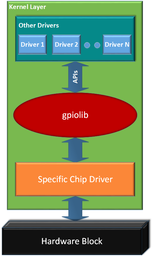
中间层是 Gpiolib,用于管理系统中的 GPIO。Gpiolib 汇总了 GPIO 的通用操作,根据 GPIO 的特性,Gpiolib 对上(其他 Drivers)提供的一套统一通用的操作 GPIO 的软件接口,屏蔽了不同芯片的具体实现。对下,Gpiolib 提供了针对不同芯片操作的一套 framework,针对不同芯片,只需要实现 Specific Chip Driver ,然后使用 Gpiolib 提供的注册函数,将其挂接到 Gpiolib 上,这样就完成了这一套东西。
对于其他驱动来说,比如 LED 灯驱动,就需要用到通用的 Gpiolib 的函数来进行 I/O 口的操作。
2、Gpiolib 相关数据结构分析
先分析数据结构,Gpiolib 其实就是围绕几个数据结构在做文章,数据结构以及抽象层次清楚了,代码自然很快。
数据结构主要定义在 include/linux/gpio/driver.h 和 /drivers/gpio/gpiolib.h 中
首先看一个数据结构,叫 struct gpio_chip (include/linux/gpio/driver.h):
struct gpio_chip {
	const char		*label;
	struct gpio_device	*gpiodev;
	struct device		*parent;
	struct module		*owner;

	int			(*request)(struct gpio_chip *chip,
						unsigned offset);
	void			(*free)(struct gpio_chip *chip,
						unsigned offset);
	int			(*get_direction)(struct gpio_chip *chip,
						unsigned offset);
	int			(*direction_input)(struct gpio_chip *chip,
						unsigned offset);
	int			(*direction_output)(struct gpio_chip *chip,
						unsigned offset, int value);
	int			(*get)(struct gpio_chip *chip,
						unsigned offset);
	int			(*get_multiple)(struct gpio_chip *chip,
						unsigned long *mask,
						unsigned long *bits);
	void			(*set)(struct gpio_chip *chip,
						unsigned offset, int value);
	void			(*set_multiple)(struct gpio_chip *chip,
						unsigned long *mask,
						unsigned long *bits);
	int			(*set_config)(struct gpio_chip *chip,
					      unsigned offset,
					      unsigned long config);
	int			(*to_irq)(struct gpio_chip *chip,
						unsigned offset);

	void			(*dbg_show)(struct seq_file *s,
						struct gpio_chip *chip);

	int			(*init_valid_mask)(struct gpio_chip *chip);

	int			base;
	u16			ngpio;
	const char		*const *names;
	bool			can_sleep;

..........

};
gpio_chip 这个数据结构一看,很多函数指针结构,明眼人秒懂,此结构是为了抽象 GPIO 的所有操作,同时适配不同芯片的一个 common 的结构,所以,这个结构是要开出去给其他芯片进行特定的操作赋值的,比如你是 Qcom 的芯片,那么你需要实现你的这些 gpio_chip 的内容。
2.1 gpio_chip 结构
一般的,在一个芯片中,针对所有的 I/O 口都会有配置,默认状态有些是 I/O 口全部默认 GPIO 输入(稳当)。一般芯片会提供管脚复用的功能(后期的 Linux 版本中,使用 pin control 来抽象),要使用 GPIO ,则首先需要配置他为 GPIO 功能,而不是其他的服用功能。
而针对 GPIO 呢,有一些通用的特性,比如设置 GPIO 的方向,读 GPIO 的电平(输入的时候),写 GPIO 的电平(输出的时候),GPIO 作为外部中断输入,等等。
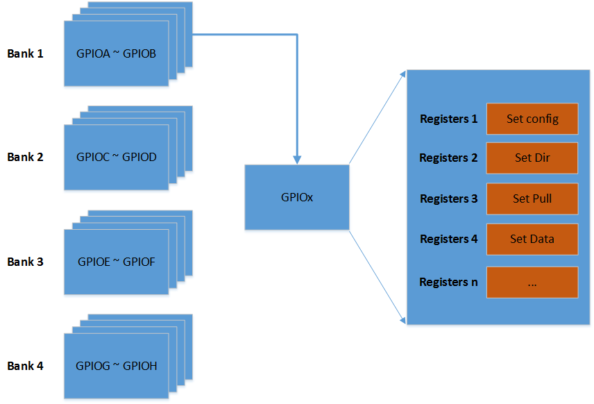
gpio_chip 的抽象,其实是对 GPIO 一组 Bank 的抽象,通常在硬件上,一个芯片对 IO 口来说,分为了很多个 Bank,每个 Bank 分为了 N 组 GPIO。
比如:1 个 SoC 将 I/O 分为了 4 个 Bank:
Bank 1:GPIOA ~ GPIOB
Bank 2:GPIOC ~ GPIOD
Bank 3:GPIOE ~ GPIOF
Bank 4:GPIOG ~ GPIOH
然鹅,每个 Bank 都有 N 组寄存器来表示 GPIO 的操作,比如:
Bank 1 中,针对 GPIO A:
GPIOA_CFG 来表示对 GPIO A 的配置
GPIOA_PULL 来表示对 GPIO A 的上下拉的配置
GPIOA_DIR 来表示对 GPIO A 配置成为输入或者输出
GPIOA_DATA 来表示 GPIO A 设置为输出的时候设置为高低或者输入的时候读高低
当然,Bank 1 中 针对 GPIO B,也是一样的操作:
GPIOB_CFG 来表示对 GPIO B 的配置
GPIOB_PULL 来表示对 GPIO B 的上下拉的配置
GPIOB_DIR 来表示对 GPIO B 配置成为输入或者输出
GPIOB_DATA 来表示 GPIO B 设置为输出的时候设置为高低或者输入的时候读高低
上面说的是一个 Bank 的情况,那么芯片有好几个 Bank,所以它们都是类似的,这里不在赘述。
所以整体结构是如下所示(这里只是打个比方,有的芯片 Bank 很多,寄存器也很多):
Linux Driver Gpiolib 对他们的抽象,使用 gpio_chip 对应了一组 Bank 描述,比如 Bank ·1,用一个 gpio_chip 来抽象:
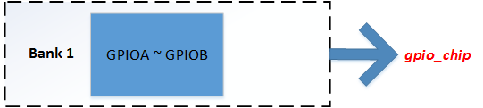
那么多个 Bank ,就用指针,或者数组来表示咯。当然这里可能说得有点不准确,gpio_chip 只是抽象了一组 Bank 的统一的接口而已。
那么对于一颗芯片底层来说,需要根据芯片手册 Datasheet,来实现这些结构的接口。
2.2 gpio_desc 结构
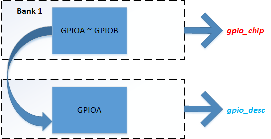
既然系统分为多个 Bank,每个 Bank 又由几组组成,那么每个 GPIO 实体就由一个 gpio_desc 来描述:
struct gpio_desc {
	struct gpio_device	*gdev;
	unsigned long		flags;
/* flag symbols are bit numbers */
#define FLAG_REQUESTED	0
#define FLAG_IS_OUT	1
#define FLAG_EXPORT	2	/* protected by sysfs_lock */
#define FLAG_SYSFS	3	/* exported via /sys/class/gpio/control */
#define FLAG_ACTIVE_LOW	6	/* value has active low */
#define FLAG_OPEN_DRAIN	7	/* Gpio is open drain type */
#define FLAG_OPEN_SOURCE 8	/* Gpio is open source type */
#define FLAG_USED_AS_IRQ 9	/* GPIO is connected to an IRQ */
#define FLAG_IRQ_IS_ENABLED 10	/* GPIO is connected to an enabled IRQ */
#define FLAG_IS_HOGGED	11	/* GPIO is hogged */
#define FLAG_TRANSITORY 12	/* GPIO may lose value in sleep or reset */

	/* Connection label */
	const char		*label;
	/* Name of the GPIO */
	const char		*name;
};
这个结构比较简单,可以看到,他包含了一个 gpio_device 的结构和 flag,以及 lable 和 name;
gdev 指针指向了这个 gpio_desc 所属的 gpio_device(马上描述),flag 代表了这个 GPIO 的属性状态;
看起来 gpio_chip 和 gpio_desc 应该是包含关系,但是 Kernel 中并没有直接将其两个结构联系上,而是通过另外一个结构将其联系在一起,这个结构就是 gpio_device。
2.3 gpio_device 结构
gpio_device 应该算是大内总管了(最新的内核有,Linux 3 版本的内核没有这个),如果说 gpio_chip 是对一个 Bank 的 GPIO 的硬件的具体抽象的话,那么 gpio_device 就是软件层面上对一个 Bank 的 GPIO 进行管理的单元,它的数据结构是:
struct gpio_device {
	int			id;
	struct device		dev;
	struct cdev		chrdev;
	struct device		*mockdev;
	struct module		*owner;
	struct gpio_chip	*chip;
	struct gpio_desc	*descs;
	int			base;
	u16			ngpio;
	const char		*label;
	void			*data;
	struct list_head        list;

#ifdef CONFIG_PINCTRL
	/*
	 * If CONFIG_PINCTRL is enabled, then gpio controllers can optionally
	 * describe the actual pin range which they serve in an SoC. This
	 * information would be used by pinctrl subsystem to configure
	 * corresponding pins for gpio usage.
	 */
	struct list_head pin_ranges;
#endif
};
在这个 gpio_device 结构中,包含了 gpio_chip(对接芯片的操作集),gpio_desc(一些 GPIO 的描述);这个结构贯穿了整个 Gpiolib,因为 gpio_device 代表的是一个 Bank,一般的 GPIO 有多个 Bank,所以 Kernel 中,对这 gpio_device 的组织是由一个 gpio_devices 的链表构成(此处是多个 device,所以后面加了 s),在 gpiolib.c:
LIST_HEAD(gpio_devices);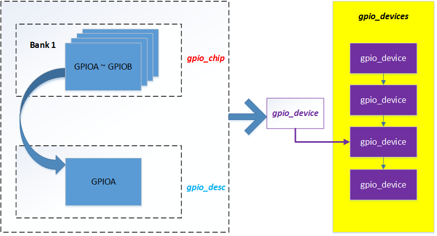
3、Gpiolib 对接芯片底层
先聊聊 Gpiolib 是怎么对接到底层实际的驱动的。在前面的 2.1 部分讲过,底层需要对接的,其实对接的部分只有那些通用的操作,其实也就是 gpio_chip 这个玩意,所以,对接底层的部分,主要关心的是这个结构体,并且对这个结构体进行赋值的过程。
在底层对接到 Gpiolib 的时候,主要是对 gpio_chip 进行实现,然后调用 gpiochip_add 的接口,向 Gpiolib 注册你的 GPIO 。
实现的过程,主要是根据芯片手册,实现对应的 GPIO 的操作,也就是说,把寄存器操作编程成为函数,对接到这个 gpio_chip 结构体上。
打个比方,对应 Exynos 4 来说:
在 gpio-exynos4.c 中:
static struct s3c_gpio_chip exynos4_gpio_common_4bit[] = {
	{
		.base	= S5P_VA_GPIO1,
		.eint_offset = 0x0,
		.group	= 0,
		.chip	= {
			.base	= EXYNOS4_GPA0(0),
			.ngpio	= EXYNOS4_GPIO_A0_NR,
			.label	= "GPA0",
		},
	}, {
		.base	= (S5P_VA_GPIO1 + 0x20),
		.eint_offset = 0x4,
		.group	= 1,
		.chip	= {
			.base	= EXYNOS4_GPA1(0),
			.ngpio	= EXYNOS4_GPIO_A1_NR,
			.label	= "GPA1",
		},
	}, {
		.base	= (S5P_VA_GPIO1 + 0x40),
		.eint_offset = 0x8,
		.group	= 2,
		.chip	= {
			.base	= EXYNOS4_GPB(0),
			.ngpio	= EXYNOS4_GPIO_B_NR,
			.label	= "GPB",
		},
	}, {
..........................................
}
定义好了各个 Bank 的基地址和 GPIO 的个数。以及支持中断的情况。
在他的初始化函数中:
static __init int exynos4_gpiolib_init(void)
{
	struct s3c_gpio_chip *chip;
	int i;
	int nr_chips;

	/* GPIO common part  */

	chip = exynos4_gpio_common_4bit;
	nr_chips = ARRAY_SIZE(exynos4_gpio_common_4bit);

	for (i = 0; i < nr_chips; i++, chip++) {
		if (chip->config == NULL)
			chip->config = &gpio_cfg;
		if (chip->base == NULL)
			pr_err("No allocation of base address for [common gpio]");
	}

	samsung_gpiolib_add_4bit_chips(exynos4_gpio_common_4bit, nr_chips);

	/* Only 4210 GPIO  part */
	if (soc_is_exynos4210()) {
		chip = exynos4210_gpio_4bit;
		nr_chips = ARRAY_SIZE(exynos4210_gpio_4bit);

		for (i = 0; i < nr_chips; i++, chip++) {
			if (chip->config == NULL)
				chip->config = &gpio_cfg;
			if (chip->base == NULL)
				pr_err("No allocation of base address [4210 gpio]");
		}

		samsung_gpiolib_add_4bit_chips(exynos4210_gpio_4bit, nr_chips);
	} else {
	/* Only 4212/4412 GPIO part */
		chip = exynos4212_gpio_4bit;
		nr_chips = ARRAY_SIZE(exynos4212_gpio_4bit);

		for (i = 0; i < nr_chips; i++, chip++) {
			if (chip->config == NULL)
				chip->config = &gpio_cfg;
			if (chip->base == NULL)
				pr_err("No allocation of base address [4212 gpio]");
		}

		samsung_gpiolib_add_4bit_chips(exynos4212_gpio_4bit, nr_chips);
	}
...................
}
调用了 xxx_gpiolib_add_xxxx 的函数,在这一些列的调用中,就将 gpio_chip 结构体相关的成员进行了赋值,并最终调用到了 gpiochip_add 函数,将其注册到了内核的 Gpiolib 子系统。大致的流程是这样的,一些细节,可能由于版本不一致,内容有细微区别。
当然,在较新的内核版本中,Kernel 提供了 devm 的接口,用于管理使用的内存情况,那么这个 gpiochip_add_data 变为了:
devm_gpiochip_add_data接下来我们看看这个注册 GPIO 的函数。
3.1、注册 GPIO 资源(gpiochip_add)
前面也说过了,注册一个 GPIO 资源使用接口:
int gpiochip_add(struct gpio_chip *chip)传入的结构是 gpio_chip,也就是一个 Bank 的描述,那么实际上, CPU 的 GPIO 控制器有多个 I/O Bank,那换句话说,需要 Kernel 管理的 GPIO Bank 的部分,都需要调用这个接口,注册进内核(当然,你也可以野蛮的 Bypass);
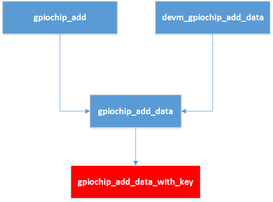
在旧的 Kernel 中,对接底层的部分,是每个 Bank 直接调用了 gpiochip_add 函数,新的内核支持传入 data,也就是带私有数据,所以新内核支持的注册接口是:gpiochip_add_data(chip, data)
他的定义是:
#define gpiochip_add_data(chip, data)
gpiochip_add_data_with_key(chip, data, NULL, NULL)
参数的含义,chip 也是 gpio_chip 的结构,data 是 void * data,私有数据。
为了兼容以前的驱动,所以在新的结构中 gpiochip_add 的定义是:
static inline int gpiochip_add(struct gpio_chip *chip)
{
	return gpiochip_add_data(chip, NULL);
}
也就是不带 data 的调用;
当然,Gpiolib 也支持带 devm 的接口,管理其内存:
int devm_gpiochip_add_data(struct device *dev, struct gpio_chip *chip,
			   void *data)
{
	struct gpio_chip **ptr;
	int ret;

	ptr = devres_alloc(devm_gpio_chip_release, sizeof(*ptr),
			     GFP_KERNEL);
	if (!ptr)
		return -ENOMEM;

	ret = gpiochip_add_data(chip, data);
	if (ret < 0) {
		devres_free(ptr);
		return ret;
	}

	*ptr = chip;
	devres_add(dev, ptr);

	return 0;
}
EXPORT_SYMBOL_GPL(devm_gpiochip_add_data);所以,可以看到,前前后后的几个注册的接口,最后全部汇集到:gpiochip_add_data_with_key
接下来就来分析一下这个接口;
3.2、gpiochip_add_data_with_key
这个函数分成几次来看,先是 part 1:
.......................
part 1 start
.......................

int gpiochip_add_data_with_key(struct gpio_chip *chip, void *data,
			       struct lock_class_key *lock_key,
			       struct lock_class_key *request_key)
{
	unsigned long	flags;
	int		status = 0;
	unsigned	i;
	int		base = chip->base;
	struct gpio_device *gdev;

	/*
	 * First: allocate and populate the internal stat container, and
	 * set up the struct device.
	 */
	gdev = kzalloc(sizeof(*gdev), GFP_KERNEL);
	if (!gdev)
		return -ENOMEM;
	gdev->dev.bus = &gpio_bus_type;
	gdev->chip = chip;
	chip->gpiodev = gdev;
	if (chip->parent) {
		gdev->dev.parent = chip->parent;
		gdev->dev.of_node = chip->parent->of_node;
	}

#ifdef CONFIG_OF_GPIO
	/* If the gpiochip has an assigned OF node this takes precedence */
	if (chip->of_node)
		gdev->dev.of_node = chip->of_node;
	else
		chip->of_node = gdev->dev.of_node;
#endif

	gdev->id = ida_simple_get(&gpio_ida, 0, 0, GFP_KERNEL);
	if (gdev->id < 0) {
		status = gdev->id;
		goto err_free_gdev;
	}
	dev_set_name(&gdev->dev, "gpiochip%d", gdev->id);
	device_initialize(&gdev->dev);
	dev_set_drvdata(&gdev->dev, gdev);
	if (chip->parent && chip->parent->driver)
		gdev->owner = chip->parent->driver->owner;
	else if (chip->owner)
		/* TODO: remove chip->owner */
		gdev->owner = chip->owner;
	else
		gdev->owner = THIS_MODULE;

.......................
part 1 end
.......................

}
part 1 中,因为传入的结构是 gpio_chip,他代表了是一个 Bank,但是并没有 gpio_device 的结构,所以,在这个函数中,首先分配一个 gpio_device 的结构,并将其结构体成员的 chip ,等等进行赋值,建立起相关的结构联系。
再看 part 2:
..............
part 2 start
..............
	gdev->descs = kcalloc(chip->ngpio, sizeof(gdev->descs[0]), GFP_KERNEL);
	if (!gdev->descs) {
		status = -ENOMEM;
		goto err_free_ida;
	}

	if (chip->ngpio == 0) {
		chip_err(chip, "tried to insert a GPIO chip with zero linesn");
		status = -EINVAL;
		goto err_free_descs;
	}

	if (chip->ngpio > FASTPATH_NGPIO)
		chip_warn(chip, "line cnt %u is greater than fast path cnt %un",
		chip->ngpio, FASTPATH_NGPIO);

	gdev->label = kstrdup_const(chip->label ?: "unknown", GFP_KERNEL);
	if (!gdev->label) {
		status = -ENOMEM;
		goto err_free_descs;
	}

	gdev->ngpio = chip->ngpio;
	gdev->data = data;
..............
part 2 end
..............
part 2 中,由于 1 个 Bank不仅仅只有一个 GPIO,所以 gpio_chip->ngpio 的结构表示了这个 Bank 一共的 GPIO 个数,每一个 GPIO 使用一个 gpio_desc 表示,所以,这里分配了 ngpio 个 descs;
最后是 part 3:
.............
part 3 start
.............
spin_lock_irqsave(&gpio_lock, flags);

	/*
	 * TODO: this allocates a Linux GPIO number base in the global
	 * GPIO numberspace for this chip. In the long run we want to
	 * get *rid* of this numberspace and use only descriptors, but
	 * it may be a pipe dream. It will not happen before we get rid
	 * of the sysfs interface anyways.
	 */
	if (base < 0) {
		base = gpiochip_find_base(chip->ngpio);
		if (base < 0) {
			status = base;
			spin_unlock_irqrestore(&gpio_lock, flags);
			goto err_free_label;
		}
		/*
		 * TODO: it should not be necessary to reflect the assigned
		 * base outside of the GPIO subsystem. Go over drivers and
		 * see if anyone makes use of this, else drop this and assign
		 * a poison instead.
		 */
		chip->base = base;
	}
	gdev->base = base;

	status = gpiodev_add_to_list(gdev);
	if (status) {
		spin_unlock_irqrestore(&gpio_lock, flags);
		goto err_free_label;
	}

	spin_unlock_irqrestore(&gpio_lock, flags);

	for (i = 0; i < chip->ngpio; i++)
		gdev->descs[i].gdev = gdev;

#ifdef CONFIG_PINCTRL
	INIT_LIST_HEAD(&gdev->pin_ranges);
#endif

	status = gpiochip_set_desc_names(chip);
	if (status)
		goto err_remove_from_list;

	status = gpiochip_irqchip_init_valid_mask(chip);
	if (status)
		goto err_remove_from_list;

	status = gpiochip_alloc_valid_mask(chip);
	if (status)
		goto err_remove_irqchip_mask;

	status = gpiochip_add_irqchip(chip, lock_key, request_key);
	if (status)
		goto err_remove_chip;

	status = of_gpiochip_add(chip);
	if (status)
		goto err_remove_chip;

	status = gpiochip_init_valid_mask(chip);
	if (status)
		goto err_remove_chip;

	for (i = 0; i < chip->ngpio; i++) {
		struct gpio_desc *desc = &gdev->descs[i];

		if (chip->get_direction && gpiochip_line_is_valid(chip, i))
			desc->flags = !chip->get_direction(chip, i) ?
					(1 << FLAG_IS_OUT) : 0;
		else
			desc->flags = !chip->direction_input ?
					(1 << FLAG_IS_OUT) : 0;
	}

	acpi_gpiochip_add(chip);

	machine_gpiochip_add(chip);

	/*
	 * By first adding the chardev, and then adding the device,
	 * we get a device node entry in sysfs under
	 * /sys/bus/gpio/devices/gpiochipN/dev that can be used for
	 * coldplug of device nodes and other udev business.
	 * We can do this only if gpiolib has been initialized.
	 * Otherwise, defer until later.
	 */
	if (gpiolib_initialized) {
		status = gpiochip_setup_dev(gdev);
		if (status)
			goto err_remove_chip;
	}
	return 0;

err_remove_chip:
	acpi_gpiochip_remove(chip);
	gpiochip_free_hogs(chip);
	of_gpiochip_remove(chip);
	gpiochip_free_valid_mask(chip);
err_remove_irqchip_mask:
	gpiochip_irqchip_free_valid_mask(chip);
err_remove_from_list:
	spin_lock_irqsave(&gpio_lock, flags);
	list_del(&gdev->list);
	spin_unlock_irqrestore(&gpio_lock, flags);
err_free_label:
	kfree_const(gdev->label);
err_free_descs:
	kfree(gdev->descs);
err_free_ida:
	ida_simple_remove(&gpio_ida, gdev->id);
err_free_gdev:
	/* failures here can mean systems won't boot... */
	pr_err("%s: GPIOs %d..%d (%s) failed to register, %dn", __func__,
	       gdev->base, gdev->base + gdev->ngpio - 1,
	       chip->label ? : "generic", status);
	kfree(gdev);
	return status;
.............
part 3 end
.............
在 part 3 中,base 代表了每个 Bank 的编号,将其赋值;然后通过 gpiodev_add_to_list(gdev) 将这个 gdev 挂到全局的 gpio_devices :
static int gpiodev_add_to_list(struct gpio_device *gdev)
{
	struct gpio_device *prev, *next;

	if (list_empty(&gpio_devices)) {
		/* initial entry in list */
		list_add_tail(&gdev->list, &gpio_devices);
		return 0;
	}

	next = list_entry(gpio_devices.next, struct gpio_device, list);
	if (gdev->base + gdev->ngpio <= next->base) {
		/* add before first entry */
		list_add(&gdev->list, &gpio_devices);
		return 0;
	}

	prev = list_entry(gpio_devices.prev, struct gpio_device, list);
	if (prev->base + prev->ngpio <= gdev->base) {
		/* add behind last entry */
		list_add_tail(&gdev->list, &gpio_devices);
		return 0;
	}

	list_for_each_entry_safe(prev, next, &gpio_devices, list) {
		/* at the end of the list */
		if (&next->list == &gpio_devices)
			break;

		/* add between prev and next */
		if (prev->base + prev->ngpio <= gdev->base
				&& gdev->base + gdev->ngpio <= next->base) {
			list_add(&gdev->list, &prev->list);
			return 0;
		}
	}

	dev_err(&gdev->dev, "GPIO integer space overlap, cannot add chipn");
	return -EBUSY;
}
接着就是设置一些 name 字段,配置中断之类的,初始化每个 desc[] 结构的 flags,最后调用:
	if (gpiolib_initialized) {
		status = gpiochip_setup_dev(gdev);
		if (status)
			goto err_remove_chip;
	}
	return 0;
然后,不出意外的话,返回 0;
这里说一下 gpiochip_setup_dev 调用,这个是在 Gpiolib init 的时候调用 gpiochip_setup_devs:
static int __init gpiolib_dev_init(void)
{
	int ret;

	/* Register GPIO sysfs bus */
	ret = bus_register(&gpio_bus_type);
	if (ret < 0) {
		pr_err("gpiolib: could not register GPIO bus typen");
		return ret;
	}

	ret = alloc_chrdev_region(&gpio_devt, 0, GPIO_DEV_MAX, "gpiochip");
	if (ret < 0) {
		pr_err("gpiolib: failed to allocate char dev regionn");
		bus_unregister(&gpio_bus_type);
	} else {
		gpiolib_initialized = true;
		gpiochip_setup_devs();
	}
	return ret;
}
core_initcall(gpiolib_dev_init);
而这个 gpiochip_setup_devs 对每一个 gpio_devicecs 节点调用:gpiochip_setup_dev:
static void gpiochip_setup_devs(void)
{
	struct gpio_device *gdev;
	int err;

	list_for_each_entry(gdev, &gpio_devices, list) {
		err = gpiochip_setup_dev(gdev);
		if (err)
			pr_err("%s: Failed to initialize gpio device (%d)n",
			       dev_name(&gdev->dev), err);
	}
}
最后到:
static int gpiochip_setup_dev(struct gpio_device *gdev)
{
	int status;

	cdev_init(&gdev->chrdev, &gpio_fileops);
	gdev->chrdev.owner = THIS_MODULE;
	gdev->dev.devt = MKDEV(MAJOR(gpio_devt), gdev->id);

	status = cdev_device_add(&gdev->chrdev, &gdev->dev);
	if (status)
		return status;

	chip_dbg(gdev->chip, "added GPIO chardev (%d:%d)n",
		 MAJOR(gpio_devt), gdev->id);

	status = gpiochip_sysfs_register(gdev);
	if (status)
		goto err_remove_device;

	/* From this point, the .release() function cleans up gpio_device */
	gdev->dev.release = gpiodevice_release;
	pr_debug("%s: registered GPIOs %d to %d on device: %s (%s)n",
		 __func__, gdev->base, gdev->base + gdev->ngpio - 1,
		 dev_name(&gdev->dev), gdev->chip->label ? : "generic");

	return 0;

err_remove_device:
	cdev_device_del(&gdev->chrdev, &gdev->dev);
	return status;
}其实就是注册了字符设备,并且添加到了 sysfs;
个人理解,因为不知道这个 init 和我们的对接底层的驱动的 init 谁先执行到,所以用了一个变量 gpiolib_initialized 来表示当前的 Gpiolib 是不是已经完成了相关的字符设备的注册,如果是 Gpiolib 先去 init 的话,那么 gpiolib_initialized ture,芯片对接底层的部分错过 gpio_chip setup 的机会,所以需要重新调用这个 gpiochip_setup_dev 接口,反之 OK;
到这里,对接底层驱动的部分基本上 OK 了,小伙伴们需要按照自己芯片的 Specific 去做自己的 gpio_chip 结构并最终通过 gpiochip_add_data 添加到 Gpiolib 子系统中;
还有一点需要注意到的是,小伙伴们需要自行定义一些结构,来获得并表示自己 Bank 的虚拟地址等等,这样才能操作到实际的硬件寄存器;
4、Gpiolib 为其他驱动提供的 APIs
在对接底层完成后,Gpiolib 为其他的驱动提供了一些列的调用接口:
1、gpio_request:向内核申请 gpio
要使用 GPIO 首先应该向内核进行申请,返回 0,代表申请成功,可以进行后续操作
2、gpio_free: 对应 gpio_request,是使用完gpio以后把gpio释放掉
3、gpio_direction_input :设置 GPIO 为输入
4、gpio_direction_output:设置 GPIO 为输出
5、gpio_get_value :读取 GPIO 的值
6、gpio_set_value:设置 GPIO 口的值
4.1、gpio_request
其他驱动使用 GPIO 的时候呢,需要先调用这个接口,向 Gpiolib 进行申请 GPIO :
int gpio_request(unsigned gpio, const char *label)
{
	struct gpio_desc *desc = gpio_to_desc(gpio);

	/* Compatibility: assume unavailable "valid" GPIOs will appear later */
	if (!desc && gpio_is_valid(gpio))
		return -EPROBE_DEFER;

	return gpiod_request(desc, label);
}
EXPORT_SYMBOL_GPL(gpio_request);
他传入的参数有一个 gpio 和一个 label,gpio 参数是一个数字,代表着板子上 GPIO 的编号,什么叫编号呢?请注意,这里的编号,有别于 Datasheet 中的编号,要知道这个,我们先好好了解一下 gpio_chip->base 的成员,打个比如,很多人都了解过三星的 2440 或者 6410 的芯片,对于他们的 GPIO 定义,我们来看看如何定义这个 gpio_chip->base 成员的:
static struct samsung_gpio_chip s3c64xx_gpios_4bit[] = {
#ifdef CONFIG_ARCH_S3C64XX
	{
		.chip	= {
			.base	= S3C64XX_GPA(0),
			.ngpio	= S3C64XX_GPIO_A_NR,
			.label	= "GPA",
		},
	}, {
		.chip	= {
			.base	= S3C64XX_GPB(0),
			.ngpio	= S3C64XX_GPIO_B_NR,
			.label	= "GPB",
		},
	}, {
		.chip	= {
			.base	= S3C64XX_GPC(0),
			.ngpio	= S3C64XX_GPIO_C_NR,
			.label	= "GPC",
		},
.......................
}
这里我们看到的 .base 就是 gpio_chip->base ,他别定义为 S3C64XX_GPA(0)、S3C64XX_GPB(0)、S3C64XX_GPC(0)......他定义在:
gpio_samsung.h
/* GPIO bank sizes */
#define S3C64XX_GPIO_A_NR	(8)
#define S3C64XX_GPIO_B_NR	(7)
#define S3C64XX_GPIO_C_NR	(8)
#define S3C64XX_GPIO_D_NR	(5)
#define S3C64XX_GPIO_E_NR	(5)
#define S3C64XX_GPIO_F_NR	(16)
#define S3C64XX_GPIO_G_NR	(7)
#define S3C64XX_GPIO_H_NR	(10)
#define S3C64XX_GPIO_I_NR	(16)
#define S3C64XX_GPIO_J_NR	(12)
#define S3C64XX_GPIO_K_NR	(16)
#define S3C64XX_GPIO_L_NR	(15)
#define S3C64XX_GPIO_M_NR	(6)
#define S3C64XX_GPIO_N_NR	(16)
#define S3C64XX_GPIO_O_NR	(16)
#define S3C64XX_GPIO_P_NR	(15)
#define S3C64XX_GPIO_Q_NR	(9)

/* GPIO bank numbes */

/* CONFIG_S3C_GPIO_SPACE allows the user to select extra
 * space for debugging purposes so that any accidental
 * change from one gpio bank to another can be caught.
*/

#define S3C64XX_GPIO_NEXT(__gpio)
	((__gpio##_START) + (__gpio##_NR) + CONFIG_S3C_GPIO_SPACE + 1)

enum s3c_gpio_number {
	S3C64XX_GPIO_A_START = 0,
	S3C64XX_GPIO_B_START = S3C64XX_GPIO_NEXT(S3C64XX_GPIO_A),
	S3C64XX_GPIO_C_START = S3C64XX_GPIO_NEXT(S3C64XX_GPIO_B),
	S3C64XX_GPIO_D_START = S3C64XX_GPIO_NEXT(S3C64XX_GPIO_C),
	S3C64XX_GPIO_E_START = S3C64XX_GPIO_NEXT(S3C64XX_GPIO_D),
	S3C64XX_GPIO_F_START = S3C64XX_GPIO_NEXT(S3C64XX_GPIO_E),
	S3C64XX_GPIO_G_START = S3C64XX_GPIO_NEXT(S3C64XX_GPIO_F),
	S3C64XX_GPIO_H_START = S3C64XX_GPIO_NEXT(S3C64XX_GPIO_G),
	S3C64XX_GPIO_I_START = S3C64XX_GPIO_NEXT(S3C64XX_GPIO_H),
	S3C64XX_GPIO_J_START = S3C64XX_GPIO_NEXT(S3C64XX_GPIO_I),
	S3C64XX_GPIO_K_START = S3C64XX_GPIO_NEXT(S3C64XX_GPIO_J),
	S3C64XX_GPIO_L_START = S3C64XX_GPIO_NEXT(S3C64XX_GPIO_K),
	S3C64XX_GPIO_M_START = S3C64XX_GPIO_NEXT(S3C64XX_GPIO_L),
	S3C64XX_GPIO_N_START = S3C64XX_GPIO_NEXT(S3C64XX_GPIO_M),
	S3C64XX_GPIO_O_START = S3C64XX_GPIO_NEXT(S3C64XX_GPIO_N),
	S3C64XX_GPIO_P_START = S3C64XX_GPIO_NEXT(S3C64XX_GPIO_O),
	S3C64XX_GPIO_Q_START = S3C64XX_GPIO_NEXT(S3C64XX_GPIO_P),
};

/* S3C64XX GPIO number definitions. */

#define S3C64XX_GPA(_nr)	(S3C64XX_GPIO_A_START + (_nr))
#define S3C64XX_GPB(_nr)	(S3C64XX_GPIO_B_START + (_nr))
#define S3C64XX_GPC(_nr)	(S3C64XX_GPIO_C_START + (_nr))
#define S3C64XX_GPD(_nr)	(S3C64XX_GPIO_D_START + (_nr))
#define S3C64XX_GPE(_nr)	(S3C64XX_GPIO_E_START + (_nr))
#define S3C64XX_GPF(_nr)	(S3C64XX_GPIO_F_START + (_nr))
#define S3C64XX_GPG(_nr)	(S3C64XX_GPIO_G_START + (_nr))
#define S3C64XX_GPH(_nr)	(S3C64XX_GPIO_H_START + (_nr))
#define S3C64XX_GPI(_nr)	(S3C64XX_GPIO_I_START + (_nr))
#define S3C64XX_GPJ(_nr)	(S3C64XX_GPIO_J_START + (_nr))
#define S3C64XX_GPK(_nr)	(S3C64XX_GPIO_K_START + (_nr))
#define S3C64XX_GPL(_nr)	(S3C64XX_GPIO_L_START + (_nr))
#define S3C64XX_GPM(_nr)	(S3C64XX_GPIO_M_START + (_nr))
#define S3C64XX_GPN(_nr)	(S3C64XX_GPIO_N_START + (_nr))
#define S3C64XX_GPO(_nr)	(S3C64XX_GPIO_O_START + (_nr))
#define S3C64XX_GPP(_nr)	(S3C64XX_GPIO_P_START + (_nr))
#define S3C64XX_GPQ(_nr)	(S3C64XX_GPIO_Q_START + (_nr))
有上面的定义可知:
Bank A base -> S3C64XX_GPA(0) -> 0
Bank B base -> S3C64XX_GPB(0) -> S3C64XX_GPIO_A_START(=0) + S3C64XX_GPIO_A_NR(=8)
Bank C base -> S3C64XX_GPC(0) -> S3C64XX_GPIO_B_START(8) + S3C64XX_GPIO_B_NR(=7)
....................
所以呢,所有的 GPIO 都是按照这个从 0 开始的顺序进行编号的,在这款芯片软件层的对接 Gpiolib 的实现上,每一个 Bank 的 base 被设计成为了上一个 GPIO 的起始位置,加上上一个 GPIO 的个数,最终得出,所有的 GPIO 都是按照顺序,在软件层面上,进行统一编号,这个 gpio_chip->base 值,就是指的每个 Bank 的起始编号!
言归正传,gpio_request 函数中的这个 gpio 入参,就是指的这些被编号了的 GPIO 的号码,你要他,就要翻他的牌!
在 gpio_request 实现中,首先调用了 gpio_to_desc 去根据传入的 gpio 的牌子,去索引到 gpio_desc 结构(还记得么,一个 gpio_desc 表征了一个 GPIO 的实例)
struct gpio_desc *gpio_to_desc(unsigned gpio)
{
	struct gpio_device *gdev;
	unsigned long flags;

	spin_lock_irqsave(&gpio_lock, flags);

	list_for_each_entry(gdev, &gpio_devices, list) {
		if (gdev->base <= gpio &&
		    gdev->base + gdev->ngpio > gpio) {
			spin_unlock_irqrestore(&gpio_lock, flags);
			return &gdev->descs[gpio - gdev->base];
		}
	}

	spin_unlock_irqrestore(&gpio_lock, flags);

	if (!gpio_is_valid(gpio))
		WARN(1, "invalid GPIO %dn", gpio);

	return NULL;
}
EXPORT_SYMBOL_GPL(gpio_to_desc);
可以看到,其实就是遍历了 gpio_devices ,然后如果你传入的编号在这个 Bank 之内,OK,给你返回这个这个 desc 结构;
然后调用到 Gpiolib 的 gpiod_request:
int gpiod_request(struct gpio_desc *desc, const char *label)
{
	int status = -EPROBE_DEFER;
	struct gpio_device *gdev;

	VALIDATE_DESC(desc);
	gdev = desc->gdev;

	if (try_module_get(gdev->owner)) {
		status = gpiod_request_commit(desc, label);
		if (status < 0)
			module_put(gdev->owner);
		else
			get_device(&gdev->dev);
	}

	if (status)
		gpiod_dbg(desc, "%s: status %dn", __func__, status);

	return status;
}
走到 gpiod_request_commit:
static int gpiod_request_commit(struct gpio_desc *desc, const char *label)
{
	struct gpio_chip	*chip = desc->gdev->chip;
	int			status;
	unsigned long		flags;
	unsigned		offset;

	spin_lock_irqsave(&gpio_lock, flags);

	/* NOTE:  gpio_request() can be called in early boot,
	 * before IRQs are enabled, for non-sleeping (SOC) GPIOs.
	 */

	if (test_and_set_bit(FLAG_REQUESTED, &desc->flags) == 0) {
		desc_set_label(desc, label ? : "?");
		status = 0;
	} else {
		status = -EBUSY;
		goto done;
	}

	if (chip->request) {
		/* chip->request may sleep */
		spin_unlock_irqrestore(&gpio_lock, flags);
		offset = gpio_chip_hwgpio(desc);
		if (gpiochip_line_is_valid(chip, offset))
			status = chip->request(chip, offset);
		else
			status = -EINVAL;
		spin_lock_irqsave(&gpio_lock, flags);

		if (status < 0) {
			desc_set_label(desc, NULL);
			clear_bit(FLAG_REQUESTED, &desc->flags);
			goto done;
		}
	}
	if (chip->get_direction) {
		/* chip->get_direction may sleep */
		spin_unlock_irqrestore(&gpio_lock, flags);
		gpiod_get_direction(desc);
		spin_lock_irqsave(&gpio_lock, flags);
	}
done:
	spin_unlock_irqrestore(&gpio_lock, flags);
	return status;
}
针对这 GPIO,如果没人去 FLAG_REQUESTED 的话,那么按照传入的 label 设置他的标签,在获得他的一些方向,等状态;
如果已经被 FLAG_REQUESTED 了的话,返回 -EBUSY,请求 GPIO 失败。
4.2、gpio_direction_input/gpio_direction_output
当 request 成功后,你就可以用你成功的这个 gpio 来搞事情了,如果要读 GPIO 状态,则需要配置成为 input,写的话,配置 output(点个 LED 灯);
这个两个函数很简单:
static inline int gpio_direction_input(unsigned gpio)
{
	return gpiod_direction_input(gpio_to_desc(gpio));
}
static inline int gpio_direction_output(unsigned gpio, int value)
{
	return gpiod_direction_output_raw(gpio_to_desc(gpio), value);
}
不在过多分析,其实就是根据传入的 gpio 的编号,也是转换成为了 desc 后,获得了 Bank 的 gpio_chip 结构,然后调用了挂接上去的 direction_input/direction_output 而已,我们看一个实际的底层实现:
static int samsung_gpiolib_4bit2_input(struct gpio_chip *chip,
				       unsigned int offset)
{
	struct samsung_gpio_chip *ourchip = to_samsung_gpio(chip);
	void __iomem *base = ourchip->base;
	void __iomem *regcon = base;
	unsigned long con;

	if (offset > 7)
		offset -= 8;
	else
		regcon -= 4;

	con = __raw_readl(regcon);
	con &= ~(0xf << con_4bit_shift(offset));
	__raw_writel(con, regcon);

	pr_debug("%s: %p: CON %08lxn", __func__, base, con);

	return 0;
}
static int samsung_gpiolib_4bit2_output(struct gpio_chip *chip,
					unsigned int offset, int value)
{
	struct samsung_gpio_chip *ourchip = to_samsung_gpio(chip);
	void __iomem *base = ourchip->base;
	void __iomem *regcon = base;
	unsigned long con;
	unsigned long dat;
	unsigned con_offset = offset;

	if (con_offset > 7)
		con_offset -= 8;
	else
		regcon -= 4;

	con = __raw_readl(regcon);
	con &= ~(0xf << con_4bit_shift(con_offset));
	con |= 0x1 << con_4bit_shift(con_offset);

	dat = __raw_readl(base + GPIODAT_OFF);

	if (value)
		dat |= 1 << offset;
	else
		dat &= ~(1 << offset);

	__raw_writel(dat, base + GPIODAT_OFF);
	__raw_writel(con, regcon);
	__raw_writel(dat, base + GPIODAT_OFF);

	pr_debug("%s: %p: CON %08lx, DAT %08lxn", __func__, base, con, dat);

	return 0;
}
4.3、gpiod_set_value/gpiod_get_value
读 GPIO 和 写 GPIO 差不多,这里不在多说,一眼便知;
最后
以上就是诚心小熊猫最近收集整理的关于Linux GPIO 驱动 (gpiolib)1、简述2、Gpiolib 相关数据结构分析3、Gpiolib 对接芯片底层4、Gpiolib 为其他驱动提供的 APIs的全部内容,更多相关Linux内容请搜索靠谱客的其他文章。


发表评论 取消回复