常用时序逻辑电路设计
- 同步时序逻辑电路
- 序列检测器
- 异步时序逻辑电路
- 窄脉冲捕获电路
- MUX同步器
- 握手协议
- 单比特脉冲信号(控制信号)传输代码:
- 多比特信号(数据信号)传输代码:
本文主要用来存放各种时序电路代码,异步时序电路分析见另一篇文章,主要是一些跨时钟域处理电路及方法。
窄脉冲捕获电路.
MUX同步器.
握手协议.
同步时序逻辑电路
序列检测器
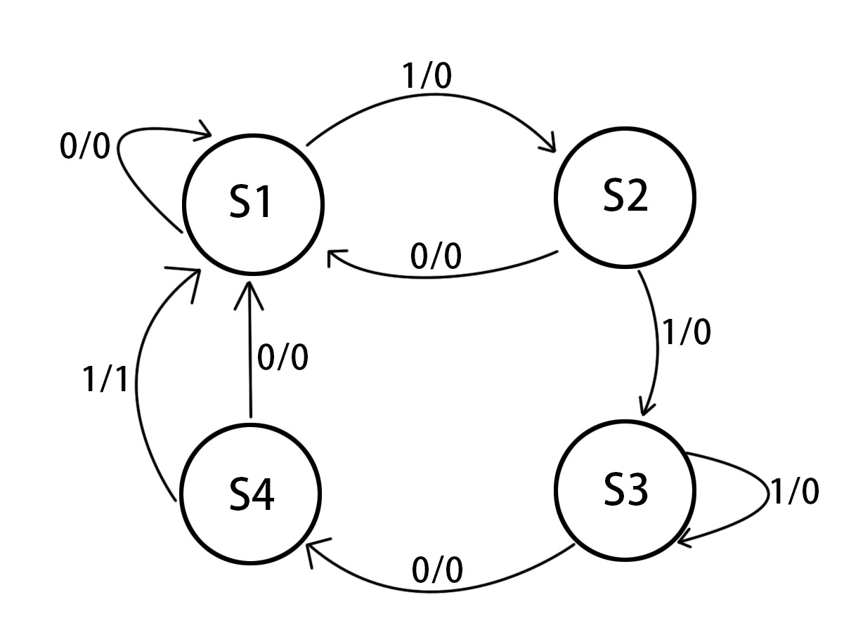
从一串二进制数据中找到指定的字符串并输出信号。找“1101”,序列为16’b1110_1010_1101_0011。
状态机:
代码:
module test(
	input	clk,
	input	rst_n,
	input	data,

	output	reg y
);

localparam	st0 = 2'b00;
localparam	st1 = 2'b01;
localparam	st2 = 2'b10;
localparam	st3 = 2'b11;

reg [1:0]	cur_stat;
reg [1:0]	nxt_stat;

//1
always @(posedge clk or negedge rst_n)begin
	if(!rst_n)
		cur_stat = st0;
	else
		cur_stat = nxt_stat;
end

//2
always @(*)begin
	case(cur_stat)
		st0:begin
			if(!data)
				nxt_stat = st0;
			else
				nxt_stat = st1;
		end
		st1:begin
			if(!data)
				nxt_stat = st0;
			else
				nxt_stat = st2;
		end
		st2:begin
			if(!data)
				nxt_stat = st3;
			else
				nxt_stat = st2;
		end
		st3:begin
			if(!data)
				nxt_stat = st0;
			else
				nxt_stat = st0;
		end
	endcase
end

//3
always @(posedge clk or negedge rst_n)begin
	if(!rst_n)
		y<=1'd0;
	else begin
		case(cur_stat)
			st0:begin
				if(!data) y<=1'd0;
				else 	y<=1'd1;
				end
			st1:y<=1'd0;
			st2:y<=1'd0;
			st3:y<=1'd0;
		endcase
	end
end

endmodule
testbench:
`timescale 1 ps/ 1 ps
module test_vlg_tst();

reg clk;
reg rst_n;
reg	[15:0]	data_t;

wire y;
wire data;

assign	data = data_t[15];
test i1 (
	.clk(clk),
	.rst_n(rst_n),
	.data(data),

	.y(y)
);
initial
begin
	rst_n = 0;
	#50 rst_n =1;
	#5000 $stop;
end

initial
begin
	clk=0;  forever #10 clk = ~clk;
end

always @(posedge clk or negedge rst_n)begin
	if(!rst_n)
		data_t <= 16'b1110_1010_1101_0011;
	else
		data_t <= (data_t << 1);
end

endmodule
仿真结果:
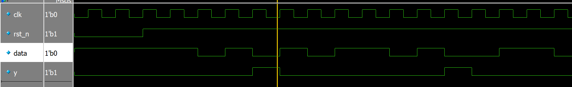
最基础的同步时序电路。
异步时序逻辑电路
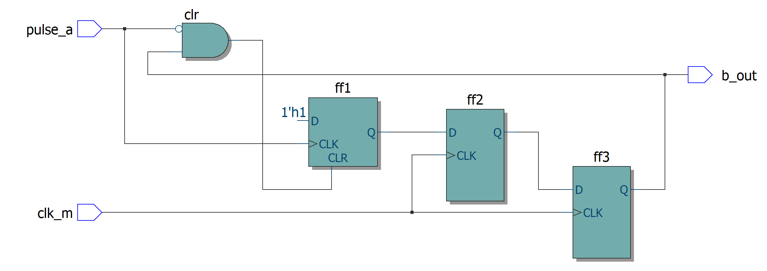
窄脉冲捕获电路
代码:
module test(
	input               clk_m,
	input               pulse_a,  //快时钟域产生的异步窄脉冲控制信号
	output		        b_out	//慢时钟域同步的宽脉冲输出
);

reg	ff1;//利用脉冲信号的上升沿进行输出脉冲信号,然后通过FF3的反馈进行清零
reg ff2;
reg ff3;//异步信号两级D触发器降低亚稳态
wire clr;

assign clr  = (!pulse_a) & ff3; //组合逻辑电路
assign b_out = ff3;

always @(posedge pulse_a or posedge clr)begin
	if(clr)
		ff1<=1'd0;
	else if(pulse_a)
		ff1<=1'd1;
	else
		ff1<=ff1;
end

always @(posedge clk_m)begin
	ff2<=ff1;
	ff3 <= ff2;
end

endmodule
testbench:
`timescale 1 ps/ 1 ps
module test_vlg_tst();

reg clk_m;
reg pulse_a;

wire b_out;

test i1 (
	.clk_m(clk_m),
	.pulse_a(pulse_a),
	.b_out(b_out)
);
initial
begin
	#50000 $stop;
end

initial
begin
	clk_m=0; #50 forever #25 clk_m = ~clk_m;
end

initial begin
	pulse_a = 1'b0;
	forever begin
	#500	pulse_a = 1'b1;
	#5	pulse_a = 1'b0;
	end
end

endmodule
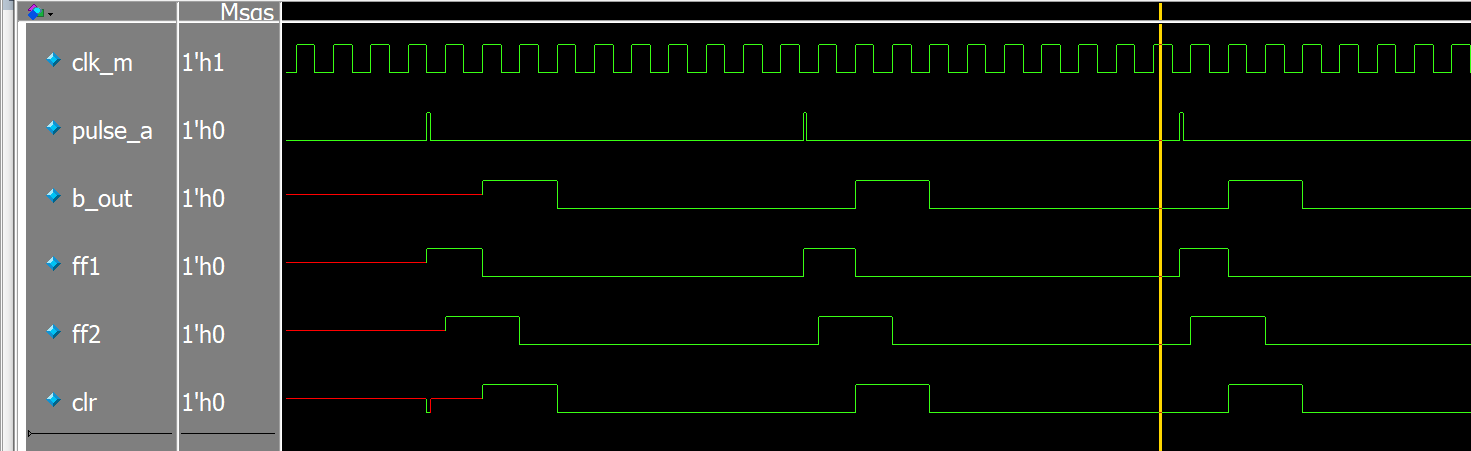
仿真:
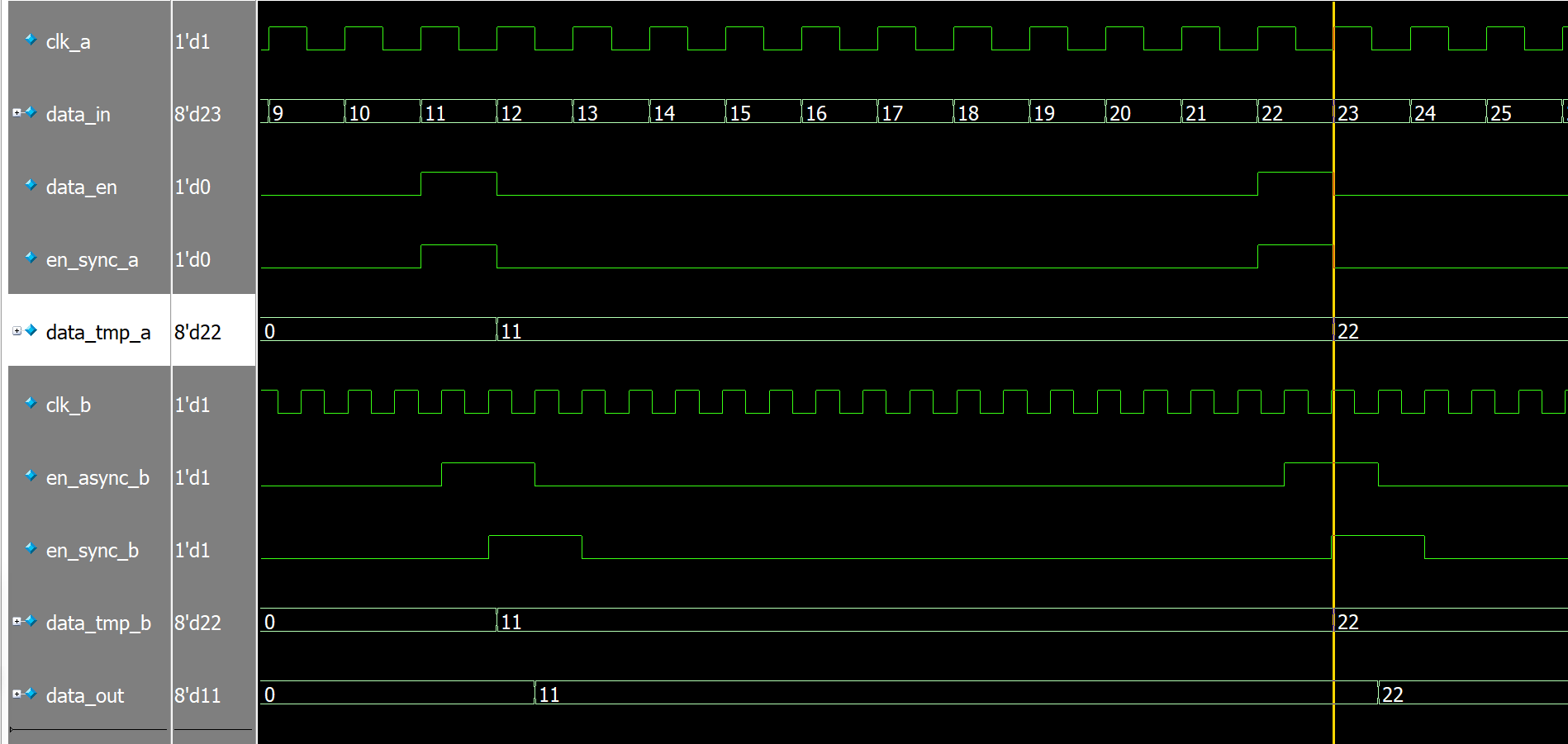
MUX同步器
链接:MUX同步器.
代码:
module test(
	input	clk_a,
	input	clk_b,
	input	rst_n,
	input	[7:0]	data_in,
	input	data_en,

	output	reg [7:0]	data_out
);

reg en_sync_a;
reg en_async_b;
reg en_sync_b;
reg [ 7:0]	data_tmp_a;
wire [7:0]	data_tmp_b;

assign	data_tmp_b = en_sync_b?data_tmp_a:data_out;
//同步clk_a的en
always @(posedge clk_a or negedge rst_n)begin
	if(!rst_n)
		en_sync_a <= 1'b0;
	else
		en_sync_a <= data_en;
end

always @(posedge clk_b or negedge rst_n)begin
	if(!rst_n)begin
		en_async_b <= 1'b0;
		en_sync_b  <= 1'b0;
	end
	else begin
		en_async_b <= en_sync_a;
		en_sync_b  <= en_async_b;
	end
end

always @(posedge clk_a or negedge rst_n)begin
	if(!rst_n)
		data_tmp_a <= 8'b0;
	else if(en_sync_a)
		data_tmp_a <= data_in;
	else
		data_tmp_a <= data_tmp_a;
end

always @(posedge clk_b or negedge rst_n)begin
	if(!rst_n)
		data_out <= 8'd0;
	else
		data_out <= data_tmp_b;
end

endmodule
testbench:
`timescale 1 ps/ 1 ps
module test_vlg_tst();

reg clk_a;
reg clk_b;
reg rst_n;
reg [7:0]	data_in = 8'd0;
reg	data_en;

wire	[7:0]	data_out;

test  i1(
	.clk_a(clk_a),
	.clk_b(clk_b),
	.rst_n(rst_n),
	.data_in(data_in),
	.data_en(data_en),

	.data_out(data_out)
);

initial begin
	rst_n = 1'b0;
	#50 rst_n =1'b1;
	#5000  $stop;
end

initial begin
	data_en = 1'b0;
	clk_a = 1'b0; forever begin #13 clk_a = ~clk_a; end
end

initial begin
	clk_b = 1'b0; forever begin #8  clk_b = ~clk_b; end
end
always @(posedge clk_a)begin
	data_in <= data_in +1'b1;
end

always begin
	#273
	data_en = 1'b1; #26;
	data_en = 1'b0; #260;
	data_en = 1'b1; #26;
	data_en = 1'b0; #130;
end

endmodule
仿真:
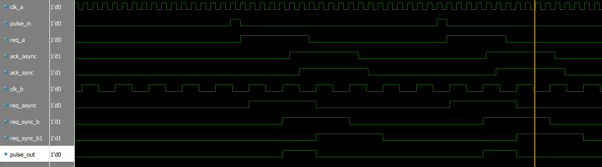
握手协议
单比特脉冲信号(控制信号)传输代码:
module test(
	input               clk_a,//快时钟
	input               clk_b,//慢时钟
	input               rst_n,
	input               pulse_in, //快时钟脉冲输入
	output              pulse_out	//慢时钟输出脉冲信号
);

reg	req_a;			//clk_a发出请求
reg	req_async;		//clk_b下 打一拍接收到的异步请求
reg	req_sync_b;		//clk_b下 打两拍接收到的同步请求
reg	req_sync_b1;	//打三拍 进行边沿检测用

reg	ack_async;		// clk_a采到的clk_b发出的异步应答信号
reg	ack_sync;		// clk_a下打一拍的同步应答信号

assign 	pulse_out =  req_sync_b & (~req_sync_b1);
//扩展脉冲pulse_in
always@(posedge clk_a or negedge rst_n)
begin
    if(!rst_n)
        req_a <= 1'b0;
    else if(pulse_in)
        req_a <= 1'b1;
    else if(ack_sync)//检测到clk_b发出的应答信号 关断req
        req_a <= 1'b0;
    else
        req_a <= req_a;
end

//req_a to clk_b //打两拍
always@(posedge clk_b or negedge rst_n)
begin
    if(!rst_n)
    begin
        req_async <= 1'b0;
        req_sync_b <= 1'b0;
        req_sync_b1 <= 1'b0;
    end
    else
    begin
        req_async <= req_a; //打拍异步请求
        req_sync_b <= req_async;//打两拍异步请求 降低亚稳态概率
        req_sync_b1 <= req_sync_b;  //打三拍异步请求 边沿检测
    end
end

//req_sync_b作为反馈信号到clk_a中作为应答信号
always@(posedge clk_a or negedge rst_n)
begin
    if(!rst_n)
    begin
        ack_async <= 1'b0;
        ack_sync <= 1'b0;
    end
    else
    begin
        ack_async <= req_sync_b;	//采集异步应答信号
        ack_sync  <= ack_async; 	//打两拍降低亚稳态
    end
end
endmodule
testbench:
`timescale 1 ps/ 1 ps
module test_vlg_tst();

reg clk_a;
reg clk_b;
reg rst_n;
reg pulse_in;
reg [5:0]	cnt;

wire pulse_out;

test i1 (
	.clk_a(clk_a),//快时钟
	.clk_b(clk_b),//慢时钟
	.rst_n(rst_n),
	.pulse_in(pulse_in), //快时钟脉冲输入
	.pulse_out(pulse_out)	//慢时钟输出脉冲信号
);
initial
begin
	rst_n = 0;
	#100 rst_n =1;
	#50000 $stop;
end

initial
begin
	clk_a=0; #25 forever #10 clk_a = ~clk_a;
end

initial
begin
	clk_b=0; #43 forever #34 clk_b = ~clk_b;
end

always @(posedge clk_a or negedge rst_n)begin
	if(!rst_n)
		pulse_in <= 1'd0;
	else if(cnt == 6'd20)
		pulse_in <= 1'd1;
	else
		pulse_in <= 1'd0;
end

always @(posedge clk_a or negedge rst_n)begin
	if(!rst_n)
		cnt <= 6'd0;
	else if(cnt == 6'd20)
		cnt <= 6'd0;
	else
		cnt <= cnt +1'd1;
end

endmodule
仿真结果:
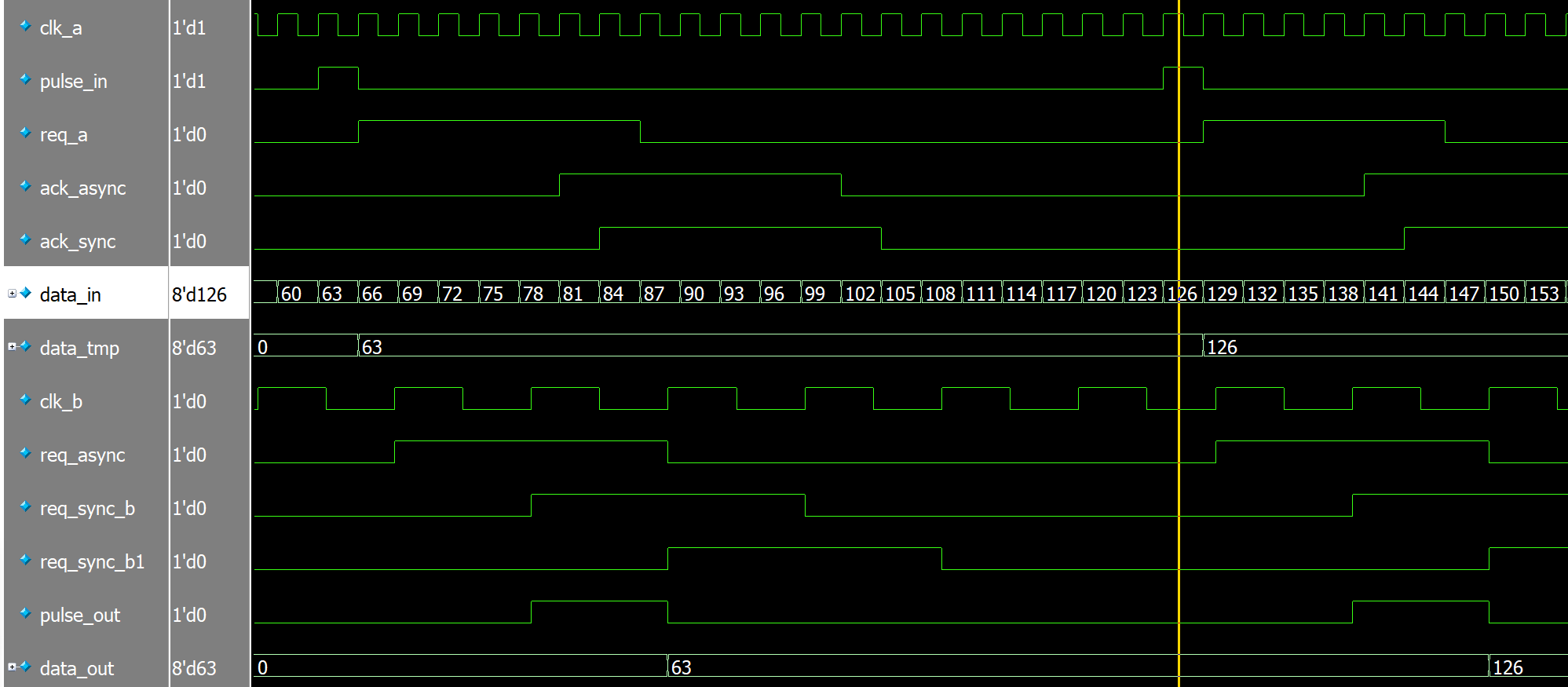
多比特信号(数据信号)传输代码:
module test(
	input               clk_a,//快时钟
	input               clk_b,//慢时钟
	input               rst_n,
	input	[7:0]		data_in, //8位数据信号
	input               pulse_in, //快时钟脉冲输入
	output              pulse_out,	//慢时钟输出脉冲信号
	output	reg [7:0]	data_out
);

reg [7:0] data_tmp; //数据缓存寄存器
reg req_a;			//clk_a发出请求
reg	req_async;		//clk_b下 打一拍接收到的异步请求
reg	req_sync_b;		//clk_b下 打两拍接收到的同步请求
reg	req_sync_b1;	//打三拍 进行边沿检测用

reg	ack_async;		// clk_a采到的clk_b发出的异步应答信号
reg	ack_sync;		// clk_a下打一拍的同步应答信号

assign 	pulse_out =  req_sync_b & (~req_sync_b1);//上升沿检测

always @(posedge clk_a or negedge rst_n)begin
	if(!rst_n)
		data_tmp <= 8'd0;
	else if(pulse_in)
		data_tmp <= data_in;
	else
		data_tmp <= data_tmp;
end

//扩展脉冲pulse_in
always@(posedge clk_a or negedge rst_n)
begin
    if(!rst_n)
        req_a <= 1'b0;
    else if(pulse_in)
        req_a <= 1'b1;
    else if(ack_sync)//检测到clk_b发出的应答信号 关断req
        req_a <= 1'b0;
    else
        req_a <= req_a;
end

//req_a to clk_b 打3拍
always@(posedge clk_b or negedge rst_n)
begin
    if(!rst_n)
    begin
        req_async <= 1'b0;
        req_sync_b <= 1'b0;
        req_sync_b1 <= 1'b0;
    end
    else
    begin
        req_async <= req_a; //打拍异步请求
        req_sync_b <= req_async;//打两拍异步请求 降低亚稳态概率
        req_sync_b1 <= req_sync_b;  //打三拍异步请求 边沿检测
    end
end

//req_sync_b作为反馈信号到clk_a中作为应答信号
always@(posedge clk_a or negedge rst_n)
begin
    if(!rst_n)
    begin
        ack_async <= 1'b0;
        ack_sync <= 1'b0;
    end
    else
    begin
        ack_async <= req_sync_b;	//采集异步应答信号
        ack_sync  <= ack_async; 	//打两拍降低亚稳态
    end
end

always @(posedge clk_b or negedge rst_n)begin
	if(!rst_n)
		data_out <= 8'd0;
	else if(pulse_out)
		data_out <= data_tmp;
	else
		data_out <= data_out;
end
endmodule
testbench:
`timescale 1 ps/ 1 ps
module test_vlg_tst();

reg clk_a;
reg clk_b;
reg rst_n;
reg pulse_in;
reg [5:0]	cnt;
reg [7:0] data_in;

wire[7:0] data_out;
wire pulse_out;

test i1 (
	.clk_a(clk_a),//快时钟
	.clk_b(clk_b),//慢时钟
	.data_in(data_in),
	.data_out(data_out),
	.rst_n(rst_n),
	.pulse_in(pulse_in), //快时钟脉冲输入
	.pulse_out(pulse_out)	//慢时钟输出脉冲信号
);
initial
begin
	rst_n = 0;
	#100 rst_n =1;
	#50000 $stop;
end

initial
begin
	clk_a=0; #25 forever #10 clk_a = ~clk_a;
end

initial
begin
	clk_b=0; #43 forever #34 clk_b = ~clk_b;
end

always @(posedge clk_a or negedge rst_n)begin
	if(!rst_n)
		pulse_in <= 1'd0;
	else if(cnt == 6'd20)
		pulse_in <= 1'd1;
	else
		pulse_in <= 1'd0;
end

always @(posedge clk_a or negedge rst_n)begin
	if(!rst_n)
		data_in <= 8'd0;
	else
		data_in <= data_in +2'd3;
end

always @(posedge clk_a or negedge rst_n)begin
	if(!rst_n)
		cnt <= 6'd0;
	else if(cnt == 6'd20)
		cnt <= 6'd0;
	else
		cnt <= cnt +1'd1;
end

endmodule
仿真结果:
最后
以上就是落寞长颈鹿最近收集整理的关于常用时序逻辑电路设计同步时序逻辑电路异步时序逻辑电路的全部内容,更多相关常用时序逻辑电路设计同步时序逻辑电路异步时序逻辑电路内容请搜索靠谱客的其他文章。
本图文内容来源于网友提供,作为学习参考使用,或来自网络收集整理,版权属于原作者所有。


发表评论 取消回复