状态机实验
- 一、任务一
- 1.画出状态跳转图
- 2.定义参数
- 3.编写代码
- 二、任务二
- 1.画出状态跳转图
- 2.原理图
- 3.编写代码
- 4.仿真
- 5.上板验证
任务需求
1、根据以下描述功能用verilog编写一段代码,并用状态机来实现该功能。
(1)状态机:实现一个测试过程,该过程包括启动准备状态、启动测试、停止测试、查询测试结果、显示测试结果、测试结束返回初始化6个状态;用时间来控制该过程,90秒内完成该过程;
(2)描述状态跳转时间;
(3)编码实现。
2. 画出可以检测10010串的状态图, 并用verilog编程实现之。
一、任务一
1.画出状态跳转图
因为该过程包括启动准备状态、启动测试、停止测试、查询测试结果、显示测试结果、测试结束返回初始化6个状态
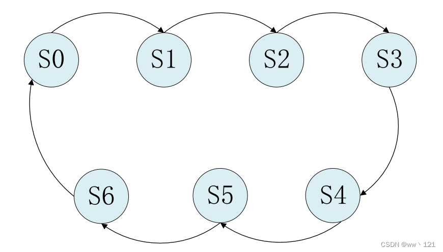
这里借鉴原子哥文档里面的插图
2.定义参数
状态跳转图画完之后,接下来通过parameter来定义各个不同状态的参数,如下代码所示:
parameter S0 = 7'b0000001; //独热码定义方式
parameter S1 = 7'b0000010;
parameter S2 = 7'b0000100;
parameter S3 = 7'b0001000;
parameter S4 = 7'b0010000;
parameter S5 = 7'b0100000;
parameter S6 = 7'b1000000;
这里是使用独热码的方式来定义状态机,每个状态只有一位为1,当然也可以直接定义成
十进制的0,1,2……7。
因为我们定义成独热码的方式,每一个状态的位宽为7位,接下来还需要定义两个7位的寄
存器,一个用来表示当前状态,另一个用来表示下一个状态,如下所示:
reg [6:0] curr_st ; //当前状态
reg [6:0] next_st ; //下一个状态
3.编写代码
我们使用三个always语句来开始编写状态机的代码
第一个always采用同步时序描述状态转移;
第二个always采用组合逻辑判断状态转移条件;
第三个always是描述状态输出
首先回顾一下原子哥以7分频为例写的状态机例子代码:
1 module divider7_fsm (
//系统时钟与复位
3 input sys_clk ,
4 input sys_rst_n ,
5
6 //输出时钟
7 output reg clk_divide_7
8 );
9
10 //parameter define
11 parameter S0 = 7'b0000001; //独热码定义方式
12 parameter S1 = 7'b0000010;
13 parameter S2 = 7'b0000100;
14 parameter S3 = 7'b0001000;
15 parameter S4 = 7'b0010000;
16 parameter S5 = 7'b0100000;
17 parameter S6 = 7'b1000000;
18
19 //reg define
20 reg [6:0] curr_st ; //当前状态
21 reg [6:0] next_st ; //下一个状态
22
23 //*****************************************************
24 //** main code
25 //*****************************************************
26
27 //状态机的第一段采用同步时序描述状态转移
28 always @(posedge sys_clk or negedge sys_rst_n) begin
29 if (!sys_rst_n)
30 curr_st <= S0;
31 else
32 curr_st <= next_st;
33 end
34
35 //状态机的第二段采用组合逻辑判断状态转移条件
36 always @(*) begin
37 case (curr_st)
38 S0: next_st = S1;
39 S1: next_st = S2;
40 S2: next_st = S3;
41 S3: next_st = S4;
42 S4: next_st = S5;
43 S5: next_st = S6;
44 S6: next_st = S0;
45 default: next_st = S0;
46 endcase
47 end
48
49 //状态机的第三段描述状态输出(这里采用时序电路输出)
50 always @(posedge sys_clk or negedge sys_rst_n) begin
51 if (!sys_rst_n)
52 clk_divide_7 <= 1'b0;
53 else if ((curr_st == S0) | (curr_st == S1) | (curr_st == S2) | (curr_st == S3))
54 clk_divide_7 <= 1'b0;
55 else if ((curr_st == S4) | (curr_st == S5) | (curr_st == S6))
56 clk_divide_7 <= 1'b1;
57 else
58 ;
59 end
60
61 endmodule
在这基础上只需稍加修改,题目要求在90秒内完成该过程,我们还需要添加一个计时器,假设每个状态15秒
修改之后代码如下所示:
module state_test (
    input sys_clk,  //系统时钟
    input sys_rst_n,  //复位信号
    output reg clk_divide_7   //输出时钟
);
  //独热码定义方式
 parameter s1 = 6'b000001;
 parameter s2 = 6'b000010;
 parameter s3 = 6'b000100;
 parameter s4 = 6'b001000;
 parameter s5 = 6'b010000;
 parameter s6 = 6'b100000;

 //reg define
 reg [5:0] curr_st ; //当前状态
 reg [5:0] next_st ; //下一个状态
 reg [29:0] cnt ; //计时器,记满15S清零
 parameter [29:0] MAX_CNT = 750_000_000; //15s  50_000_000✖15

 //计数器
 always @(posedge sys_clk or negedge sys_rst_n) begin
     if (!sys_rst_n) begin
         cnt<=1'b0;
     end
     else if(cnt == MAX_CNT-1)
         cnt<=1'b0;
     else
         cnt<=1'b0;
 end

 //状态机的第一段采用同步时序描述状态转移
 always @(posedge sys_clk or negedge sys_rst_n) begin
 if (!sys_rst_n)
 curr_st <= s1;
 else
 curr_st <= next_st;
 end

 //状态机的第二段采用组合逻辑判断状态转移条件
 always @(*) begin
 case (curr_st)
     s1:begin
         if(cnt==MAX_CNT-1)
             next_st=s2;
     end
     s2:begin
         if(cnt==MAX_CNT-1)
             next_st=s3;
     end
     s3:begin
         if(cnt==MAX_CNT-1)
             next_st=s4;
     end
     s4:begin
         if(cnt==MAX_CNT-1)
             next_st=s5;
     end
     s5:begin
         if(cnt==MAX_CNT-1)
             next_st=s6;
     end
     s6:begin
         if(cnt==MAX_CNT-1)
             next_st=s1;
     end
 default: next_st= s1;
 endcase
 end

 //状态机的第三段描述状态输出(这里采用时序电路输出)
 always @(posedge sys_clk or negedge sys_rst_n) begin
 if (!sys_rst_n)
 clk_divide_7 <= 1'b0;
 else if ((curr_st == s1) | (curr_st == s2) | (curr_st == s3))
 clk_divide_7 <= 1'b0;
 else if ((curr_st == s4) | (curr_st == s5) | (curr_st == s6))
 clk_divide_7 <= 1'b1;
 else
 ;
 end


endmodule
二、任务二
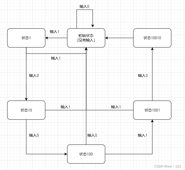
1.画出状态跳转图
题目要求程序以检测10010串,相当于校验密码
我们设置了6个状态:
①S0:初始状态,等待输入信号,检测到输入1进入S1
②S1:状态1,检测到输入0进入S2,输入1回到S0
③S2:状态10,检测到输入0进入S3,输入1回到S0
④S3:状态100,检测到输入1进入S4,输入0回到S0
⑤S4:状态1001,检测到输入0进入S5,输入1回到S0
⑥S5:状态10010,检测到字串10010,led灯亮
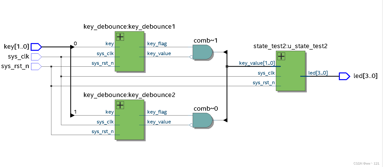
2.原理图
3.编写代码
按键消抖模块:
module key_debounce(
input sys_clk, //外部50M时钟
input sys_rst_n, //外部复位信号,低有效

input key, //外部按键输入

output reg key_flag, //按键数据有效信号
output reg key_value //按键消抖后的数据
);

//reg define
reg [31:0] delay_cnt; //延时计数
reg key_reg;

parameter MAX_CNT = 32'd1_000_000;

//*****************************************************
//** main code
//*****************************************************
always @(posedge sys_clk or negedge sys_rst_n) begin
if (!sys_rst_n) begin
 key_reg <= 1'b1;
delay_cnt <= 32'd0;
end
else begin
key_reg <= key;
if(key_reg != key)  //一旦检测到按键状态发生变化(有按键被按下或释放)
delay_cnt <= MAX_CNT;  //给延时计数器重新装载初始值(计数时间为20ms)
else if(key_reg == key) begin  //在按键状态稳定时,计数器递减,开始20ms倒计时
if(delay_cnt > 32'd0)
delay_cnt <= delay_cnt - 1'b1;
else
delay_cnt <= delay_cnt;
end
end
end

always @(posedge sys_clk or negedge sys_rst_n) begin
if (!sys_rst_n) begin
key_flag <= 1'b0;
key_value <= 4'b1;
end
else begin
if(delay_cnt == 32'd1) begin //当计数器递减到1时,说明按键稳定状态维持了20ms
key_flag <= 1'b1; //此时消抖过程结束,给出一个时钟周期的标志信号
key_value <= key; //并寄存此时按键的值
end
else begin
key_flag <= 1'b0;
key_value <= key_value;
end
end
end

endmodule
验证密码:
module state_test2 (
    input sys_clk,  //系统时钟
    input sys_rst_n,  //复位信号
    input [1:0] key_value,  //消抖之后的按键信号
    output reg[3:0] led
);
  //独热码定义方式
 parameter s0 = 6'b000001;
 parameter s1 = 6'b000010;
 parameter s2 = 6'b000100;
 parameter s3 = 6'b001000;
 parameter s4 = 6'b010000;
 parameter s5 = 6'b100000;

 //reg define
 reg [5:0] curr_st ; //当前状态
 reg [5:0] next_st ; //下一个状态

 //状态机的第一段采用同步时序描述状态转移
 always @(posedge sys_clk or negedge sys_rst_n) begin
 if (!sys_rst_n)begin
     curr_st <= s0;
 end
 else
 curr_st <= next_st;
 end


 always @(posedge sys_clk or negedge sys_rst_n) begin
     if(!sys_rst_n) begin
         next_st<=s0;
     end
     else begin
         case (curr_st)
             s0:begin
                 if(key_value[1])begin
                     next_st<=s1;
                 end
                 else if(key_value[0])begin
                     next_st<=s0;
                 end
                 else begin
                 end
             end
             s1:begin
                 if(key_value[0])begin

                     next_st<=s2;
                 end
                 else if(key_value[1])begin
                     next_st<=s0;
                 end
                 else begin
                 end
             end
             s2:begin
                 if(key_value[0])begin

                     next_st<=s3;
                 end
                 else if(key_value[1])begin
                     next_st<=s0;
                 end
                 else begin
                 end
             end
             s3:begin
                 if(key_value[1])begin

                     next_st<=s4;
                 end
                 else if(key_value[0])begin
                     next_st<=s0;
                 end
                 else begin
                 end
             end
             s4:begin
                 if(key_value[0])begin
                     next_st<=s5;
                 end
                 else if(key_value[1])begin
                     next_st<=s0;
                 end
                 else begin
                 end
             end
             s5:begin
                    next_st<=s0;
             end
         default: next_st<= s0;
         endcase
     end
 end

 //状态机的第三段描述状态输出(这里采用时序电路输出)
 always @(posedge sys_clk or negedge sys_rst_n) begin
     if (!sys_rst_n)
         led<=4'b0000;
     else if (curr_st==s5)
         led<=4'b1111;
     else
         led<=led;
 end


endmodule
顶层文件:
module top_module (
    input sys_clk,
    input sys_rst_n,
    input [1:0] key,
    output  [3:0] led
);
wire [1:0] key_value;
wire [1:0] key_flag;
//例化按键消抖模块 key1
key_debounce key_debounce1(
    .sys_clk   (sys_clk),
    .sys_rst_n (sys_rst_n),
    .key       (key[0]),
    .key_value (key_value[0]),
    .key_flag  (key_flag[0])
);
//例化按键消抖模块 key2
key_debounce key_debounce2(
    .sys_clk   (sys_clk),
    .sys_rst_n (sys_rst_n),
    .key       (key[1]),
    .key_value (key_value[1]),
    .key_flag  (key_flag[1])
);
//例化状态机模块
state_test2 u_state_test2(
    .sys_clk   (sys_clk),
    .sys_rst_n (sys_rst_n),
    .key_value ({key_flag[1]&~key_value[1],key_flag[0]&~key_value[0]}),
    .led       (led)
);
endmodule
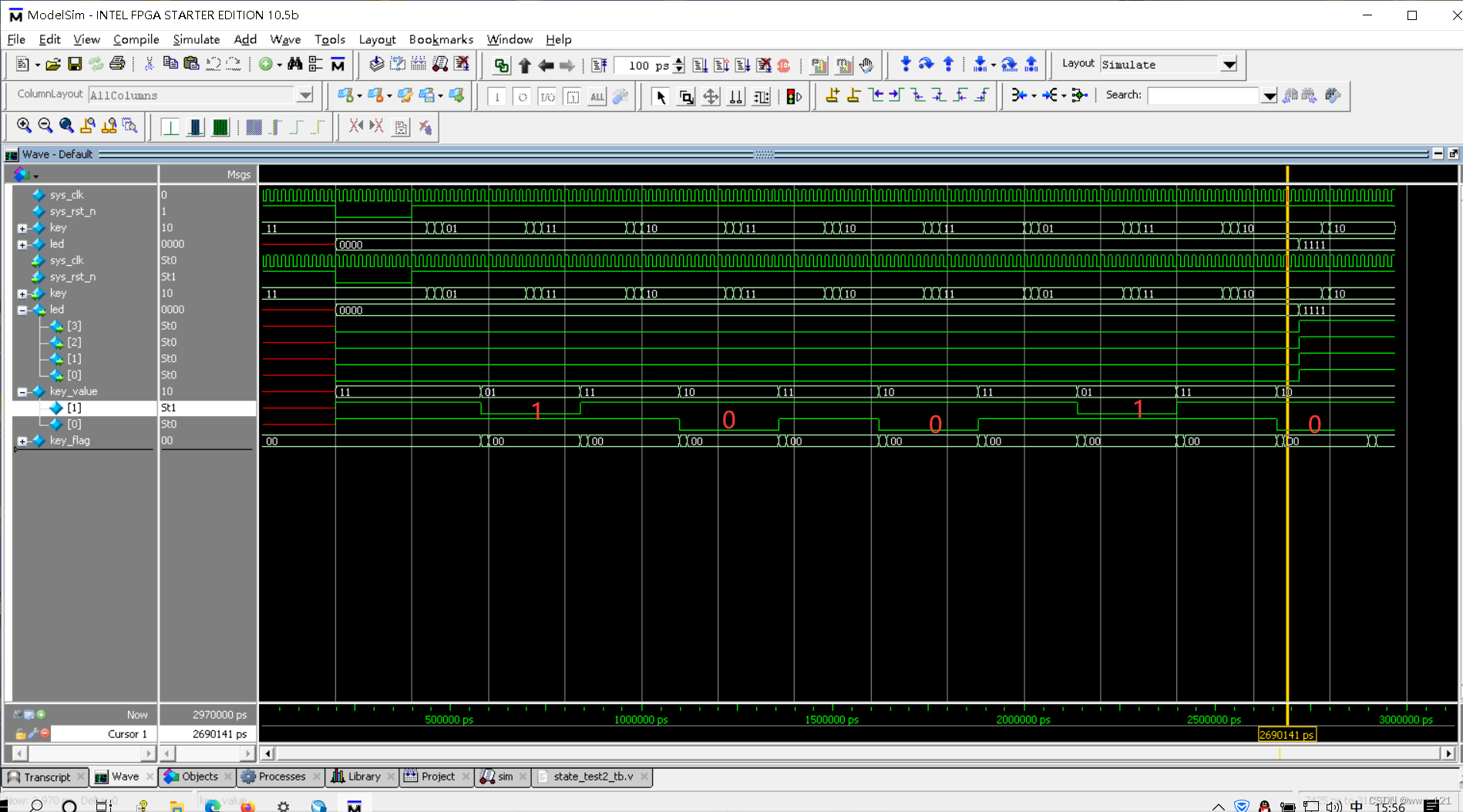
4.仿真
代码:
`timescale 1ns/1ps
module state_test2_tb();
    reg         sys_clk;
    reg         sys_rst_n;
    reg  [1:0]  key;
    wire [3:0]  led;
    defparam u_top_module.key_debounce1.MAX_CNT=5;
    defparam u_top_module.key_debounce2.MAX_CNT=5;
    top_module u_top_module(
    .sys_clk       (sys_clk)         ,
    .sys_rst_n     (sys_rst_n)       ,
    .key           (key)             ,
    .led           (led)
    );

    always #10 sys_clk = ~sys_clk;

    initial begin
        sys_clk   = 1'b1;
        sys_rst_n = 1'b1;
        key       = 2'b11;
        #200;
        sys_rst_n = 1'b0; //复位
        #200;
        sys_rst_n = 1'b1;
        //按键抖动
        #20 key  = 2'b11; //模拟抖动
        #20 key  = 2'b01; //模拟抖动
        #20 key  = 2'b11; //模拟抖动
        #20 key  = 2'b01; //按下按键1
        #200 key = 2'b01; //模拟抖动
        #20 key  = 2'b11; //模拟抖动
        #20 key  = 2'b01; //模拟抖动
        #20 key  = 2'b11; //松开按键1

        #200 key = 2'b11; //模拟抖动
        #20 key  = 2'b10; //模拟抖动
        #20 key  = 2'b11; //模拟抖动
        #20 key  = 2'b10; //按下按键0
        #200 key = 2'b10; //模拟抖动
        #20 key  = 2'b11; //模拟抖动
        #20 key  = 2'b10; //模拟抖动
        #20 key  = 2'b11; //松开按键0

        #200 key = 2'b11; //模拟抖动
        #20 key  = 2'b10; //模拟抖动
        #20 key  = 2'b11; //模拟抖动
        #20 key  = 2'b10; //按下按键0
        #200 key = 2'b10; //模拟抖动
        #20 key  = 2'b11; //模拟抖动
        #20 key  = 2'b10; //模拟抖动
        #20 key  = 2'b11; //松开按键0

        #200 key = 2'b11; //模拟抖动
        #20 key  = 2'b01; //模拟抖动
        #20 key  = 2'b11; //模拟抖动
        #20 key  = 2'b01; //按下按键1
        #200 key = 2'b01; //模拟抖动
        #20 key  = 2'b11; //模拟抖动
        #20 key  = 2'b01; //模拟抖动
        #20 key  = 2'b11; //松开按键1

        #200 key = 2'b11; //模拟抖动
        #20 key  = 2'b10; //模拟抖动
        #20 key  = 2'b11; //模拟抖动
        #20 key  = 2'b10; //按下按键0
        #200 key = 2'b10; //模拟抖动
        #20 key  = 2'b11; //模拟抖动
        #20 key  = 2'b10; //模拟抖动
        #170 key = 2'b11; //松开按键0
        $stop;
    end


endmodule
5.上板验证
最后
以上就是魔幻蜡烛最近收集整理的关于【FPGA】状态机实验一、任务一二、任务二的全部内容,更多相关【FPGA】状态机实验一、任务一二、任务二内容请搜索靠谱客的其他文章。


![[从零开始学习FPGA编程-33]:进阶篇 - 基本时序电路-寄存器(Verilog语言)](https://www.shuijiaxian.com/files_image/reation/bcimg23.png)


发表评论 取消回复